
Understanding the 4 Way Electrical Switch Wiring Diagram
Controlling a single light fixture from three or more locations requires a specific configuration that goes beyond standard single-pole or 3-way setups. At the heart of this multi-location control is the 4-way switch. Unlike a 3-way switch, which has three terminals (one common, two travelers), a 4-way switch features four terminals plus a ground. It acts as a reversing switch, crossing the traveler wires to complete or break the circuit between the two flanking 3-way switches.
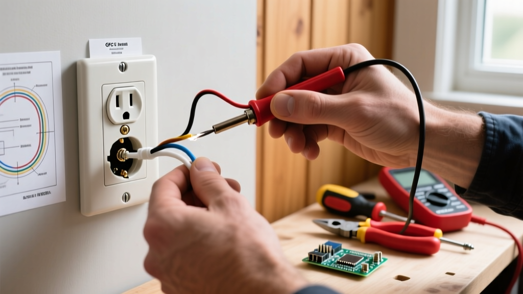
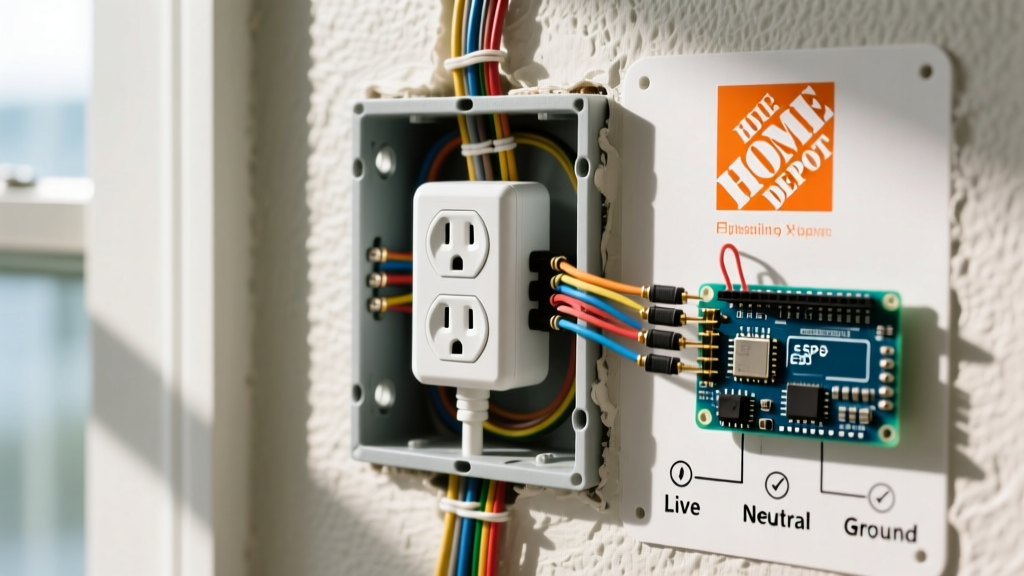
Whether you are upgrading a long hallway, a multi-entry stairwell, or a large primary bedroom, mastering the 4 way electrical switch wiring diagram is essential for a safe, code-compliant installation. This guide provides a step-by-step installation walkthrough, incorporating 2026 National Electrical Code (NEC) standards, specific product recommendations, and advanced troubleshooting techniques.
Tools, Materials, and Box Fill Requirements
Before pulling any wire, you must ensure your materials and electrical boxes can handle the increased wire volume. A 4-way switch requires two 14/3 NM-B (Romex) cables for the traveler runs, significantly increasing the box fill compared to a standard switch.
Essential Tools & Components
- Switch: Leviton Decora 15 Amp 4-Way Switch (Model # R62-05604-2WS, approx. $14) or Lutron Diva 15 Amp 4-Way (Model # DV-104P-WH, approx. $38).
- Wire: 14/3 NM-B with ground (for 15A circuits) or 12/3 NM-B (for 20A circuits). Expect to pay $0.65 to $0.85 per linear foot in 2026.
- Connectors: Wago 221 Lever Nuts (2, 3, and 5-port). These provide a more reliable, vibration-resistant connection than traditional twist-on wire nuts and save crucial space in the box.
- Testing: Fluke 1AC-II Non-Contact Voltage Tester and a standard digital multimeter.
- Stripping: Klein Tools 11055 Wire Strippers.
NEC Article 314: Box Fill Calculation
According to the National Fire Protection Association (NFPA) NEC guidelines, you must calculate box fill to prevent overheating. For 14 AWG wire, each current-carrying conductor counts as 2.0 cubic inches. A 4-way switch box will typically contain 4 current-carrying travelers, 1 equipment grounding conductor (counts as 1), and the switch yoke (counts as 2). Total allowance required: 14 cubic inches minimum. Always use deep gang boxes (minimum 22.5 cubic inches) for 4-way switch locations to ensure adequate heat dissipation and physical working room.
Step-by-Step 4-Way Switch Installation
Safety is paramount. The Occupational Safety and Health Administration (OSHA) strictly mandates Lockout/Tagout (LOTO) procedures when working on energized systems. Never rely solely on a wall switch to kill power.
Step 1: Power Isolation and Verification
- Turn off the circuit breaker controlling the lighting circuit at the main panel.
- Apply a physical lockout tag to the breaker panel to prevent accidental re-energizing.
- Test the existing switches and light fixture with your Fluke 1AC-II tester, then verify with a multimeter at the switch terminals (Line to Ground should read 0.00V).
Step 2: Wiring the First 3-Way Switch (Power Source)
The 4-way switch does not connect directly to the power source or the load; it sits in the middle. We begin at the first 3-way switch where the 14/2 NM-B power enters.
- Connect the incoming bare copper ground to the box grounding pigtail and the switch green terminal.
- Connect the incoming white (neutral) wire directly to the white neutral of the 14/3 traveler cable using a Wago 221 connector. Note: Neutrals bypass standard 4-way and 3-way switches unless you are installing smart switches requiring a neutral.
- Connect the incoming black (hot) wire to the Common (Dark Screw) terminal on the first 3-way switch.
- Connect the black and red wires of the outgoing 14/3 traveler cable to the two Brass (Traveler) terminals on the 3-way switch.
Step 3: Wiring the 4-Way Switch (The Core Diagram)
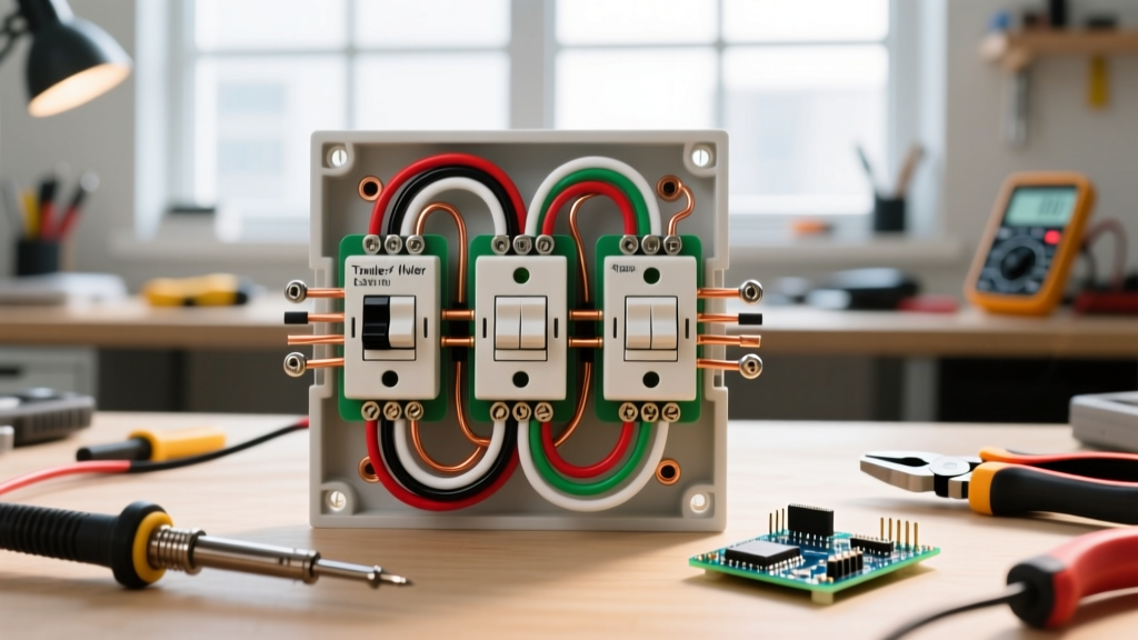
This is where the 4 way electrical switch wiring diagram comes into play. You will have two 14/3 cables entering this box: one from the first 3-way, and one heading to the second 3-way.
Expert Tip: Many modern 4-way switches label their terminals as "Line 1 / Load 1" and "Line 2 / Load 2" or "In / Out". If unlabeled, they are typically grouped by screw color (e.g., two brass screws on top, two black screws on bottom). Never mix cables between these pairs.
- Grounding: Pigtail all bare copper grounds together and attach to the switch's green grounding screw per NEC 250.148.
- Neutrals: Splice the white neutral wires from both 14/3 cables together. Cap them securely; they do not land on the switch.
- Cable 1 (From First 3-Way): Connect the black and red traveler wires to the first pair of terminals on the 4-way switch (e.g., the two brass screws).
- Cable 2 (To Second 3-Way): Connect the black and red traveler wires to the second pair of terminals on the 4-way switch (e.g., the two black screws).
Step 4: Wiring the Second 3-Way Switch (The Load)
- Connect the incoming 14/3 ground and the outgoing 14/2 ground to the switch ground screw.
- Splice the incoming white neutral from the 14/3 to the outgoing white neutral of the 14/2 load cable.
- Connect the black and red travelers from the 14/3 cable to the two Brass (Traveler) terminals.
- Connect the black (hot) wire of the 14/2 load cable (heading to the light fixture) to the Common (Dark Screw) terminal.
Traveler Wire Mapping & Color Coding Table
Maintaining consistent color coding across your traveler runs is the most critical aspect of a successful multi-way installation. The Consumer Product Safety Commission (CPSC) frequently cites reversed polarity and misidentified travelers as leading causes of residential electrical faults.
| Cable Type | Wire Color | Function in 4-Way Circuit | NEC Compliance Note |
|---|---|---|---|
| 14/2 NM-B (Source) | Black | Always Hot (Line) | Connects to 1st 3-Way Common |
| 14/2 NM-B (Source) | White | Neutral | Bypasses switches, goes to load |
| 14/3 NM-B (Traveler 1) | Black & Red | Traveler Pair A | Must land on same terminal color pair |
| 14/3 NM-B (Traveler 1) | White | Neutral | Bypasses 4-way switch entirely |
| 14/3 NM-B (Traveler 2) | Black & Red | Traveler Pair B | Must land on opposite terminal color pair |
| 14/2 NM-B (Load) | Black | Switched Hot (Load) | Connects to 2nd 3-Way Common |
Smart Home Alternatives: Bypassing the 4-Way Diagram
If you are retrofitting an older home in 2026 and find that pulling new 14/3 traveler wires through finished drywall is impossible, consider a smart switch ecosystem. Systems like the Lutron Caseta bypass the need for physical 4-way traveler wiring entirely. By installing a Lutron Caseta Smart Dimmer at the primary switch location and using wireless Pico Remotes at the secondary and tertiary locations, you eliminate the 4-way switch and traveler wires from the circuit. This requires capping the old travelers in the wall and converting the secondary boxes into simple blank covers or wireless mount plates, saving hours of drywall repair and wire fishing.
Troubleshooting Common 4-Way Failure Modes
Even with a perfect 4 way electrical switch wiring diagram, mistakes happen. Use this diagnostic matrix to identify issues before tearing open the walls.
Symptom: Light only turns on/off from one specific switch location
- Root Cause: Traveler wires are crossed or miswired at the 4-way switch. One pair of travelers is likely split between the "In" and "Out" terminal sets instead of being kept as distinct pairs.
- Fix: Turn off power. Ensure both wires from Cable 1 are on the brass screws, and both wires from Cable 2 are on the black screws.
Symptom: Breaker trips immediately upon turning on the light
- Root Cause: A dead short. Usually caused by a bare copper ground wire touching a brass traveler terminal, or a white neutral wire mistakenly wired to a traveler terminal.
- Fix: Inspect all terminal connections. Ensure wire insulation is stripped exactly 3/4 inch and no bare copper is exposed outside the terminal clamp.
Symptom: Switch feels warm to the touch during normal operation
- Root Cause: Overloaded circuit or loose terminal connection causing high resistance (arcing). Standard 15A switches are rated for roughly 1800W. If you are running high-draw halogen or incandescent arrays, you may be exceeding the switch rating.
- Fix: Calculate total fixture wattage. Upgrade to a 20A heavy-duty 4-way switch and verify 12 AWG wire is used throughout the circuit, or switch to low-draw LED fixtures.
Final Inspection and Safety Check
Before installing the wall plate, perform a final visual inspection. Verify that no bare ground wires are resting against the side terminal screws. Gently tug on every Wago connector and terminal screw to ensure a firm mechanical grip. Once the switches are screwed into the deep gang box, ensure the faceplate sits flush without bowing, which can indicate wire overcrowding. Restoring power and testing all three locations will confirm your 4-way circuit is fully operational, safe, and ready for daily use.