
Introduction to EZ Outlet Extenders in Modern Wiring
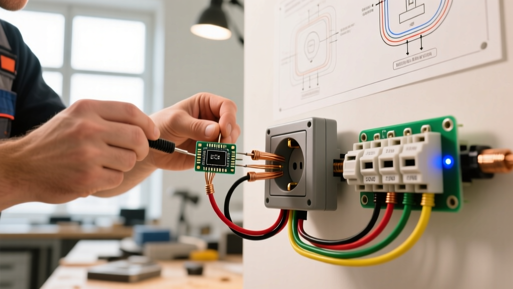
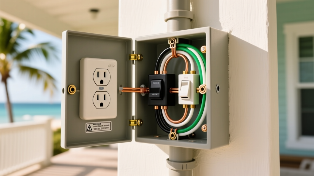
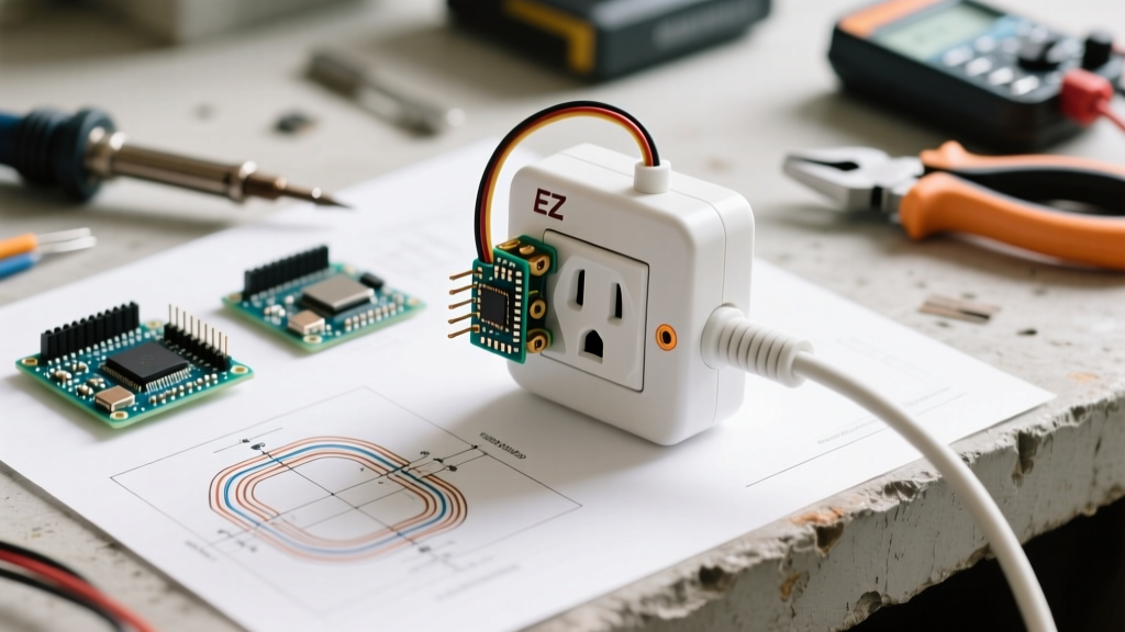
The EZ Outlet electrical outlet extender has become a staple for DIYers and electricians looking to bring recessed receptacles flush with baseboards, bypass damaged wall plates, or integrate high-wattage USB-C charging ports without tearing into drywall. Unlike standard plug-in multi-taps, a true screw-terminal EZ Outlet electrical outlet extender bridges the connection directly to the existing duplex receptacle's side-wire terminals, effectively creating a new, flush-mounted face. While highly convenient, these devices introduce new points of failure. As of 2026, with the proliferation of 240W USB-C PD 3.1 chargers and high-draw smart home hubs, inspecting and testing these extenders is critical to preventing thermal creep and series arc faults.
⚠️ CRITICAL SAFETY WARNING: Always de-energize the circuit at the main breaker panel and verify zero voltage using a non-contact voltage tester (NCVT) and a digital multimeter before removing any wall plates or touching terminal screws. According to the U.S. Consumer Product Safety Commission (CPSC), loose connections and overloaded extension devices are leading causes of residential electrical fires.Phase 1: Visual and Mechanical Inspection
Before applying power, a thorough mechanical inspection ensures the physical integrity of the extender. The housing must withstand the thermal stress of a continuous 15A or 20A load.
1. Housing and Material Verification
- Material Check: Verify the housing is made of high-impact, flame-retardant polycarbonate or thermoset urea. Avoid extenders with cheap ABS plastic, which softens at lower temperatures (around 80°C) and can deform under continuous load.
- UL/ETL Listing: Look for the holographic UL or ETL mark. Uncertified extenders often lack internal brass busbars, relying instead on thin copper-alloy stampings that increase contact resistance.
- Physical Damage: Inspect for hairline cracks near the mounting ears. A cracked ear will prevent the extender from seating flush against the wall, creating a hazardous gap where dust and moisture can accumulate.
2. Terminal Screw and Pigtail Inspection
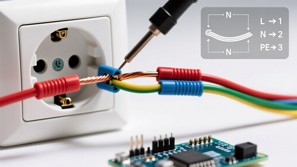
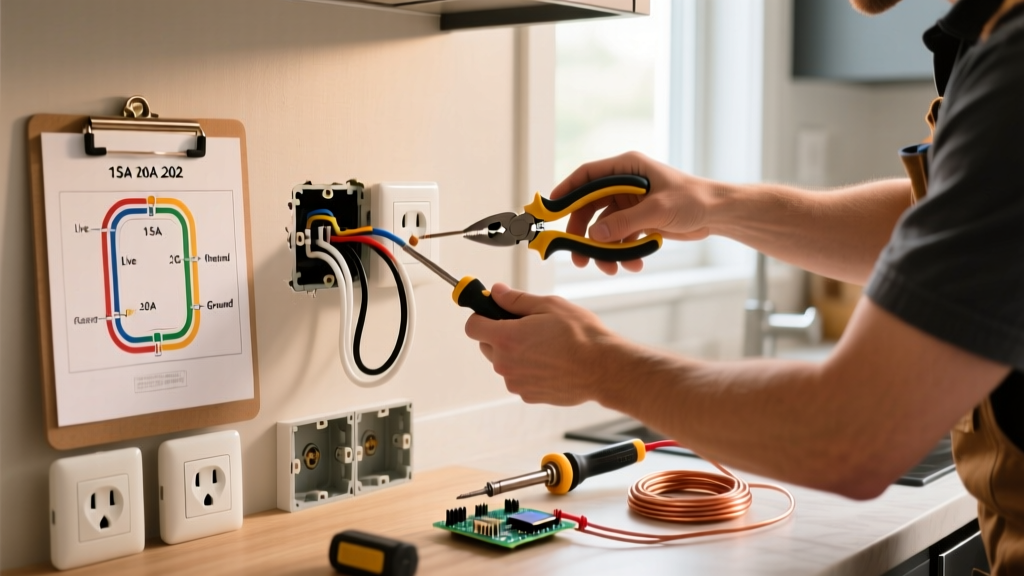
If your EZ Outlet electrical outlet extender uses pigtails to connect to the upstream receptacle, inspect the wire ferrules or spade connectors. For direct-screw models, ensure the terminal screws are not stripped. The recommended torque for 14 AWG and 12 AWG copper wire on standard brass terminal screws is between 12 and 14 inch-pounds. Under-torqued screws are the primary cause of high-resistance connections, leading to localized heating and eventual melting of the extender housing.
Phase 2: Electrical Testing Protocol
Once the extender is physically installed and the circuit is re-energized, proceed with electrical validation. You will need a True RMS digital multimeter (such as the Fluke 117) and a dedicated receptacle tester (like the Klein Tools RT250).
Step-by-Step Testing Sequence
- Polarity and Wiring Verification: Insert the RT250 into the extender's receptacle. The indicator lights must confirm correct wiring (Right/Center lights illuminated). A reading of 'Open Ground' or 'Reverse Polarity' indicates a failure in the extender's internal busbar connections or the upstream wiring.
- Voltage Drop Test: Measure the voltage at the main panel's breaker terminal, then measure the voltage at the EZ Outlet extender under zero load. A drop greater than 3% (roughly 3.6V on a 120V circuit) suggests high resistance in the upstream wiring or the extender's internal contacts.
- Ground Continuity (Millivolt Test): Set your multimeter to measure millivolts (mV). Place one probe on the known good ground at the panel and the other on the extender's ground pin. Any reading above 50mV indicates a compromised ground path, which will prevent the breaker from tripping efficiently during a fault.
- GFCI/AFCI Trip Testing: If the circuit is protected by an upstream GFCI or AFCI breaker, use the 'TEST' button on your receptacle tester. The breaker must trip within 20 to 30 milliseconds. If it fails to trip, the extender's ground pin is not making adequate contact with the internal grounding busbar.
Phase 3: Thermal and Load Testing
Electrical testing under zero load does not reveal contact resistance issues. To properly inspect an EZ Outlet electrical outlet extender, you must subject it to a simulated maximum load and monitor thermal signatures.
The 80% Continuous Load Test
Plug in a resistive load bank or a high-draw appliance (such as a 1500W space heater or a 12A shop vacuum) to draw approximately 12.5 Amps. Allow the load to run for 30 minutes. Using an infrared thermometer or a thermal imaging camera (like the FLIR TG165), scan the extender's faceplate and terminal areas.
- Acceptable Delta T: The temperature rise (Delta T) of the extender housing compared to ambient room temperature should not exceed 30°C (54°F).
- Failure Indicator: If the area immediately surrounding the hot (brass) terminal screw is more than 15°C hotter than the neutral (silver) side, you have a high-resistance connection on the hot busbar. De-energize immediately and re-torque or replace the unit.
Testing Integrated USB-C PD Ports
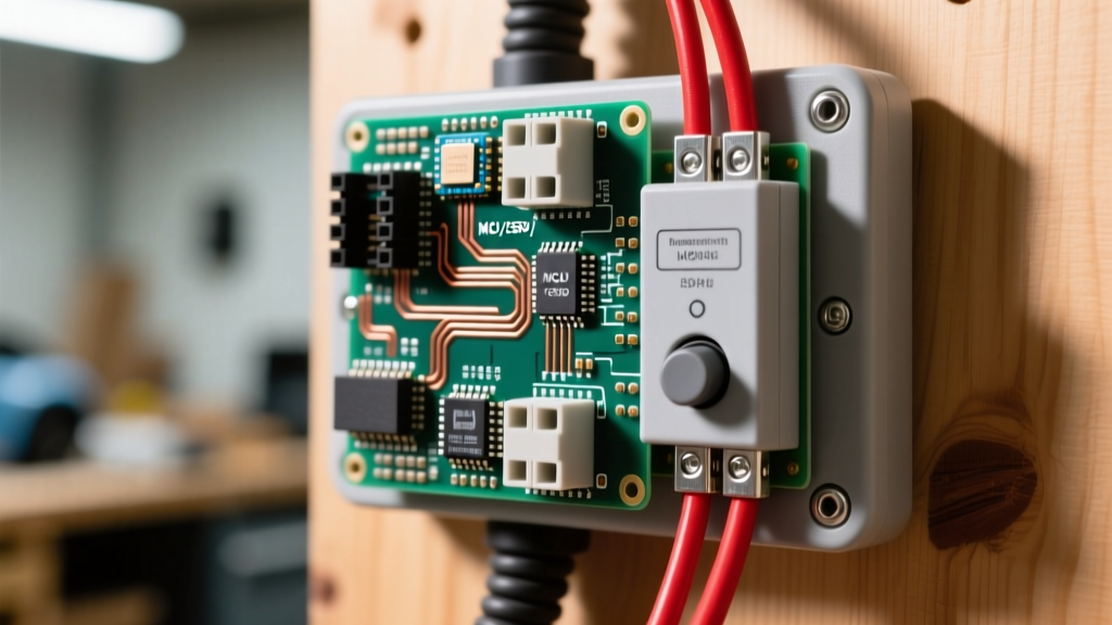
Many 2026-era EZ Outlet extenders feature integrated USB-C Power Delivery ports rated for 30W to 65W. To test these, plug in a USB-C PD electronic load tester. Draw the maximum rated wattage for 15 minutes. Monitor the internal switching power supply area (usually located in the center of the yoke). If the plastic faceplate becomes too hot to touch (exceeding 60°C), the internal heat sink is inadequate, and the unit poses a long-term fire risk.
Troubleshooting Matrix: Failure Modes & Diagnostics
Use the following matrix to quickly diagnose issues encountered during the inspection of your EZ Outlet electrical outlet extender.
| Symptom | Probable Cause | Diagnostic Tool | Corrective Action |
|---|---|---|---|
| Receptacle tester shows 'Open Ground' | Extender ground pin not contacting upstream receptacle ground slot, or internal ground strap broken. | Klein RT250, Multimeter Continuity | Adjust extender depth collar; replace if internal strap is severed. |
| Localized heat on Hot terminal (>40°C rise) | Under-torqued terminal screw or oxidation on upstream receptacle side-wire connection. | FLIR Thermal Camera, Torque Screwdriver | De-energize, clean brass contacts, torque to 14 in-lbs. |
| USB-C port intermittently disconnects | Voltage drop below 110V triggering USB-C PD controller reset, or inadequate internal heat dissipation. | USB-C PD Load Tester, True RMS DMM | Verify upstream voltage; ensure extender is not buried behind insulating furniture. |
| AFCI Breaker nuisance tripping | Series arc fault caused by loose pigtail spade connector or poor internal busbar stamping. | Visual Inspection, Arc Fault Simulator | Replace extender with a UL-listed model featuring solid brass internal busbars. |
NEC Compliance: Box Fill and Depth Constraints
When installing an EZ Outlet electrical outlet extender, you must consider the National Electrical Code (NEC) regulations regarding box fill and device depth. While the extender itself sits outside the wall cavity, its mounting mechanism and the upstream receptacle it attaches to may push the overall assembly deeper into the box.
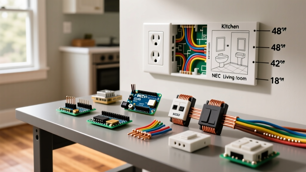
NEC Article 314.16 (Box Fill Calculations): The volume of a wiring enclosure shall not be less than the sum of the volumes required for each conductor, device, and clamp within the box. Adding deep-backbody receptacles or extenders that force wires into tight bends can violate box fill limits, especially in older 12-cubic-inch shallow metal boxes.
If your existing wall box is already crowded with three 12 AWG Romex cables, pigtails, and wire nuts, forcing an EZ Outlet extender into place can crush the insulation on the conductors. This creates a ground fault risk and can damage the series arc fault integrity of the circuit. Always calculate your box fill before installing deep-profile extenders.
Pros and Cons: Extenders vs. Traditional Box Replacement
Is the EZ Outlet electrical outlet extender the right choice for your project, or should you cut the drywall and install a new old-work box? Consider this expert breakdown:
The Advantages
- Zero Drywall Repair: Eliminates the need for patching, mudding, and painting, saving 2-4 hours of labor per outlet.
- Modernization: Instantly adds 2026-standard USB-C PD 3.1 ports to older homes without running new dedicated circuits.
- Flush Mounting: Solves the 'recessed outlet' problem caused by thick baseboards or stone veneer installations.
The Limitations
- Thermal Bottleneck: Relies entirely on the upstream receptacle's terminal grip. If the original receptacle is 15 years old, its internal contacts may already be degraded.
- Depth Issues: Can interfere with shallow furniture placement, negating the very reason it was installed.
- Cost: High-quality, surge-protected, UL-listed extenders retail between $22 and $38, making them more expensive than a standard $4 duplex receptacle and $2 old-work box.
Final Inspection Sign-Off
A properly installed and tested EZ Outlet electrical outlet extender is a safe, code-compliant solution for modernizing residential power access. By adhering to strict torque specifications, verifying ground continuity under load, and monitoring thermal signatures with IR diagnostics, you ensure the device operates safely within its UL 498 parameters. For more comprehensive guidelines on residential wiring safety and arc-fault protection, always consult the latest resources from the National Fire Protection Association (NFPA) and your local Authority Having Jurisdiction (AHJ).