
The Intersection of Cosplay and Electrical Engineering
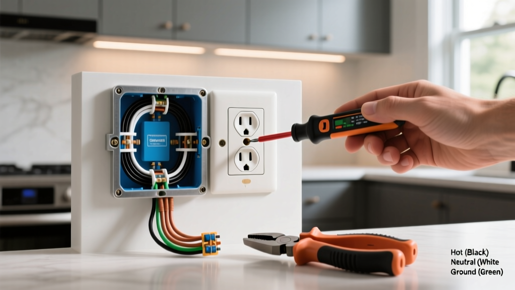
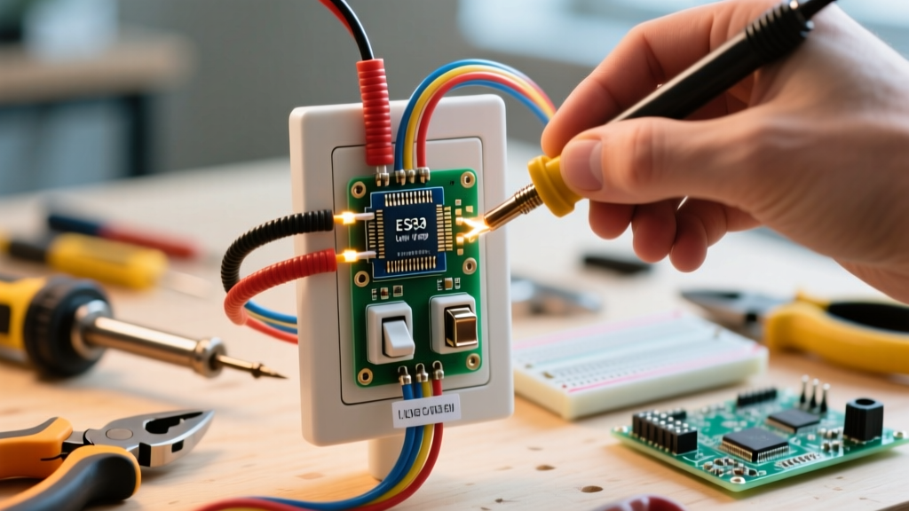
Creating a wearable prop that mimics real-world electrical infrastructure requires a careful balance of aesthetic accuracy and strict safety protocols. An electrical outlet costume is a standout choice for maker faires, Halloween, or cosplay events, but executing it properly means avoiding the dangerous temptation of using mains voltage. In this guide, we will treat the electronic assembly of your costume as a low-voltage 'installation' project, applying real-world wiring principles, circuit math, and soldering techniques to create a safe, illuminated, and highly durable wearable duplex receptacle.
CRITICAL SAFETY WARNING: Never wire a wearable costume to 120V AC mains power or use exposed high-voltage components. The human body's resistance drops significantly when sweating inside a costume, making even minor AC leakage potentially lethal. This installation guide strictly utilizes 5V DC power via USB power banks, adhering to low-voltage safety standards.
Bill of Materials (BOM) and Tooling
Before beginning the installation phase, gather the following components. Prices reflect average 2026 market rates for hobbyist electronics.
- Base Material: 10mm EVA foam craft sheets (approx. $12 for a multi-pack) for the rigid faceplate, and 5mm EVA foam for body straps.
- Illumination: Six 5mm flanged warm-white LEDs (3.2V Forward Voltage, 20mA). Cost: ~$4 for a 50-pack.
- Current Limiting: Six 100-ohm, 1/4W carbon film resistors. Cost: ~$2.
- Wiring: 22 AWG stranded silicone wire in red and black (highly flexible, high heat resistance). Cost: ~$15 per spool.
- Power Source: 10,000mAh 5V USB power bank with a minimum 2A output. Cost: ~$20.
- Switchgear: SPST (Single Pole Single Throw) miniature toggle switch, rated for at least 3A/125V (overkill for 5V, but ensures longevity). Cost: ~$3.
- Consumables: 63/37 rosin-core solder, heat shrink tubing (assorted sizes), and hot glue.
Required Tooling
For the wiring installation, you will need a temperature-controlled soldering station (set to 320°C for lead-free or 300°C for 63/37 leaded solder), a digital multimeter for continuity testing, wire strippers, and a flush cutter. For the foam crafting, a sharp utility knife, a heat gun for shaping, and acrylic paints are essential.
Phase 1: Scaling and Crafting the Faceplate
A standard US duplex receptacle faceplate measures roughly 2.75 inches by 4.5 inches. To make the costume visually striking and proportionate to a human torso, we will scale this up by a factor of 3.5. Your target dimensions for the main EVA foam chest piece will be approximately 9.6 inches wide by 15.75 inches tall.
- Cut the Base: Use a straight edge and sharp blade to cut the 10mm EVA foam to the scaled dimensions.
- Carve the Receptacles: Mark two standard outlet slots (one above the other, separated by 4 inches). Use a Dremel or a heated wire cutter to hollow out the slots to a depth of 8mm, leaving a 2mm backing layer of foam to mount the LEDs against.
- Prime and Paint: Seal the foam with 2-3 coats of flexible Plasti Dip or Mod Podge to prevent the acrylic paint from cracking when the foam bends. Paint the faceplate a high-gloss 'electrical white' and use a fine brush to paint the carved slots a deep, matte black to simulate the recessed plug holes.
Phase 2: Circuit Design and Resistor Math
Proper electrical installation requires calculating your load to prevent component failure or fire. We are powering six warm-white LEDs from a 5V DC USB source. You cannot wire LEDs directly to a 5V source without current limiting, or they will draw excessive current, overheat, and burn out.
The Calculation
Our chosen LEDs have a Forward Voltage (Vf) of 3.2V and a target Forward Current (If) of 20mA (0.02A). Using Ohm's Law, we calculate the required resistance (R) for each LED:
- Voltage Drop across Resistor: V_source - V_LED = 5V - 3.2V = 1.8V
- Resistance Required: R = V / I = 1.8V / 0.02A = 90 Ohms
The nearest standard E12 series resistor is 100 Ohms. Using a 100-ohm resistor will result in a current draw of 18mA per LED. This is well within the safe operating area, provides excellent brightness, and slightly extends your battery life. The power dissipated by each resistor is P = I²R = (0.018)² * 100 = 0.0324 Watts, meaning a standard 1/4W (0.25W) resistor is more than adequate.
Phase 3: The Low-Voltage Installation
Now we move to the physical wiring installation. Because this is a wearable, we will wire all six LED-resistor pairs in parallel. This ensures that if one LED fails, the rest remain illuminated, and each receives the full 5V from the power bank.
Step-by-Step Soldering
According to best practices outlined in SparkFun's through-hole soldering tutorial, proper wetting and joint inspection are critical for flexible wearable electronics that will endure movement.
- Prep the LEDs: Identify the anode (long leg, positive) and cathode (short leg, negative). Bend the legs 90 degrees near the base so they sit flush against the foam backing.
- Install Resistors: Solder a 100-ohm resistor to the anode of each LED. Cover the exposed joint and the resistor leads with 3mm heat shrink tubing to prevent short circuits against neighboring wires.
- Run the Bus Wires: Cut two long lengths of 22 AWG red (positive) and black (negative) silicone wire. These will act as your main 5V bus lines running down the back of the foam faceplate.
- Solder the Parallel Connections: Solder the free end of each resistor to the red bus wire. Solder the cathode of each LED directly to the black bus wire. Apply a small dab of hot glue over each solder joint to act as a strain relief, which is vital for costumes that will flex during wear.
Phase 4: Switchgear and Power Integration
An electrical outlet costume needs a way to simulate 'tripping the breaker' or turning the power on and off. We will install the SPST toggle switch at the bottom edge of the foam faceplate.
- Mount the Switch: Cut a small hole at the bottom center of the faceplate. Insert the toggle switch and secure it with its provided hex nut.
- Interrupt the Positive Line: Cut the red bus wire near the switch. Solder one end to the switch's input terminal and the other to the output terminal. Never switch the ground (black) wire in DC circuits; always break the positive line for safety.
- Terminate for USB: At the end of your bus wires, solder a female micro-USB or USB-C pigtail connector (depending on your power bank's output). Secure this pigtail to the back of the foam with a hot-glue strain relief loop.
For wearability, attach heavy-duty nylon webbing straps to the back of the 10mm foam using contact cement and rivets. Place the 10,000mAh power bank in a dedicated pouch on the waist belt to keep the weight off your chest and neck. A standard 10,000mAh bank running a 108mA total load (6 LEDs x 18mA) will theoretically power the costume for over 90 hours, far exceeding the runtime of any single event.
Troubleshooting the Installation
Even with meticulous planning, low-voltage wearable installations can encounter issues. Use the matrix below to diagnose common faults.
| Symptom | Probable Cause | Diagnostic & Fix |
|---|---|---|
| LEDs flicker when walking | Strain-induced cold solder joint or broken 22 AWG wire. | Use a multimeter in continuity mode to probe the bus lines while flexing the foam. Re-solder and add hot glue strain relief. |
| LEDs glow dimly or unevenly | Voltage drop due to wire gauge being too thin, or a missing resistor. | Verify 5V at the furthest LED using a multimeter. If below 4.5V, upgrade bus wires to 20 AWG. Check for missing 100-ohm resistors. |
| Power bank shuts off after 30 seconds | Current draw is too low for the power bank's auto-sleep feature. | Some 2026 smart power banks shut off if draw is under 50mA. Add a 10-ohm 'dummy load' resistor across the 5V line to draw an extra 50mA and keep the bank awake. |
| Toggle switch feels hot | Short circuit bypassing the LEDs. | Immediately disconnect power. Check for exposed wire strands bridging the red and black bus lines. Apply heat shrink tubing. |
Final Thoughts on Wearable Electronics
Building an electrical outlet costume is a fantastic exercise in practical, low-voltage wiring. By treating the assembly as a legitimate electrical installation—complete with load calculations, proper wire gauges, and strain relief—you ensure the prop is not only visually authentic but inherently safe. For further reading on managing power in wearable tech and avoiding voltage sag in portable battery setups, refer to the Adafruit NeoPixel Uberguide, which offers excellent foundational advice on DC power distribution for costumes. Stay safe, respect the limits of low-voltage DC, and enjoy your illuminated creation.