
Mastering Your First Electric Outlet Install
Replacing or installing a standard 120-volt receptacle is a foundational skill for any DIYer. However, an electric outlet install is not simply about connecting wires; it is about ensuring mechanical integrity, thermal stability, and strict adherence to the National Electrical Code (NEC). A poorly terminated receptacle can lead to high-resistance connections, thermal cycling, and ultimately, electrical fires.
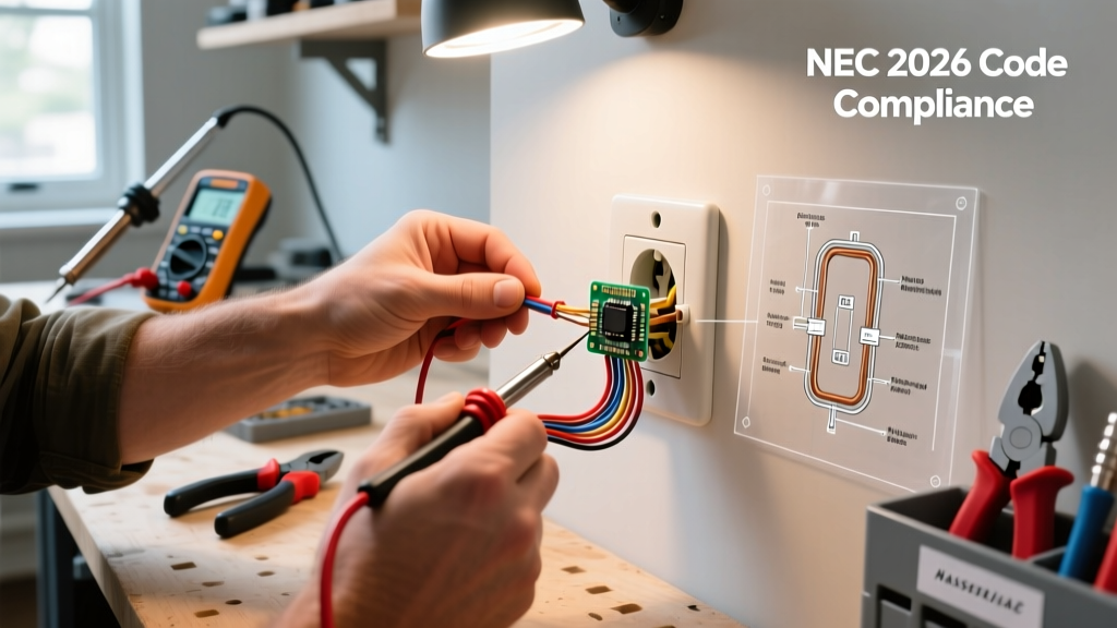
This guide strips away the fluff and provides a professional-grade, step-by-step tutorial for installing a standard 15-amp or 20-amp duplex receptacle. We will cover exact tool requirements, NEC 2023/2026 code mandates, and the physics behind proper wire termination.
Essential Tools and Materials
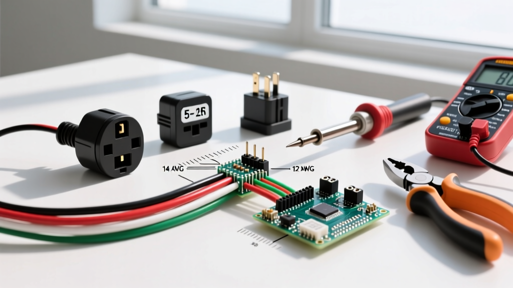
Professional electricians do not rely on guesswork or cheap multi-tools. To ensure a safe and code-compliant installation, you need precision instruments. Below is the exact loadout required for a standard residential install.
| Category | Recommended Model | Estimated Cost (2026) | Purpose |
|---|---|---|---|
| Voltage Tester | Fluke 2AC II VoltAlert | $35.00 | Non-contact verification of de-energized circuits. |
| Wire Strippers | Klein Tools 11055 | $24.00 | Precision stripping for 14 AWG and 12 AWG solid copper. |
| Torque Screwdriver | Klein Tools 706-4 | $115.00 | Calibrated tightening to meet NEC 110.14(D) standards. |
| Receptacle | Leviton 5262-SW (15A TR) | $3.50 | Tamper-resistant, commercial-grade duplex outlet. |
| Wire Connectors | Ideal 341 Wire-Nut (Red) | $0.15/ea | Pigtailing multiple wires securely. |
Code Compliance: What the NEC Demands
Before touching a screwdriver, you must understand the legal and safety frameworks governing your install. According to the National Fire Protection Association (NFPA 70), modern electrical installs must adhere to several critical mandates:
1. Tamper-Resistant (TR) Mandate
Under NEC Article 406.12, all 15-amp and 20-amp receptacles installed in dwelling units must be Tamper-Resistant (TR). These outlets feature internal shutter mechanisms that prevent foreign objects from being inserted into a single slot. If you are doing an electric outlet install in a home built before 2008, you are still legally required to upgrade to TR receptacles when replacing old units.
2. AFCI and GFCI Protection Zones
While the receptacle itself might be standard, the circuit protecting it likely requires advanced breakers. The Consumer Product Safety Commission (CPSC) heavily emphasizes ground-fault and arc-fault protection to prevent shocks and fires.
- GFCI (Ground Fault Circuit Interrupter): Required in kitchens, bathrooms, garages, outdoors, and within 6 feet of any water source.
- AFCI (Arc Fault Circuit Interrupter): Required in bedrooms, living rooms, hallways, and closets to detect dangerous electrical arcing.
Step-by-Step Execution Protocol
Step 1: De-Energize and Verify
Turn off the circuit breaker at the main panel. Do not rely on the wall switch. Use your Fluke 2AC II to test the top and bottom slots of the existing outlet. Critical: Always test your voltage tester on a known live circuit before and after testing the dead circuit to ensure the tool's battery hasn't failed mid-job.
Step 2: Prep the Wires and Box
Remove the old receptacle and inspect the wiring. Standard 15-amp circuits use 14 AWG wire (white insulation or bare copper with black insulation), while 20-amp circuits use 12 AWG wire. If you find 12 AWG wire, you must use a 20-amp rated receptacle (like the Leviton 5262-SW is 15A; you would need the 5362-SW for 20A). Ensure the bare copper ground wire is securely bonded to the back of the metal box or the green ground screw of a plastic box.
Step 3: Precision Stripping
Do not guess the strip length. Look at the back of the Leviton 5262-SW receptacle. You will find a physical "strip gauge" molded into the plastic. For standard side-wiring, this is exactly 3/4 of an inch. Use the Klein Tools 11055 strippers to remove precisely this amount of insulation. Stripping too little leaves insulation under the screw head (causing a loose connection); stripping too much exposes bare wire, creating a short-circuit hazard.
Step 4: The J-Hook Termination
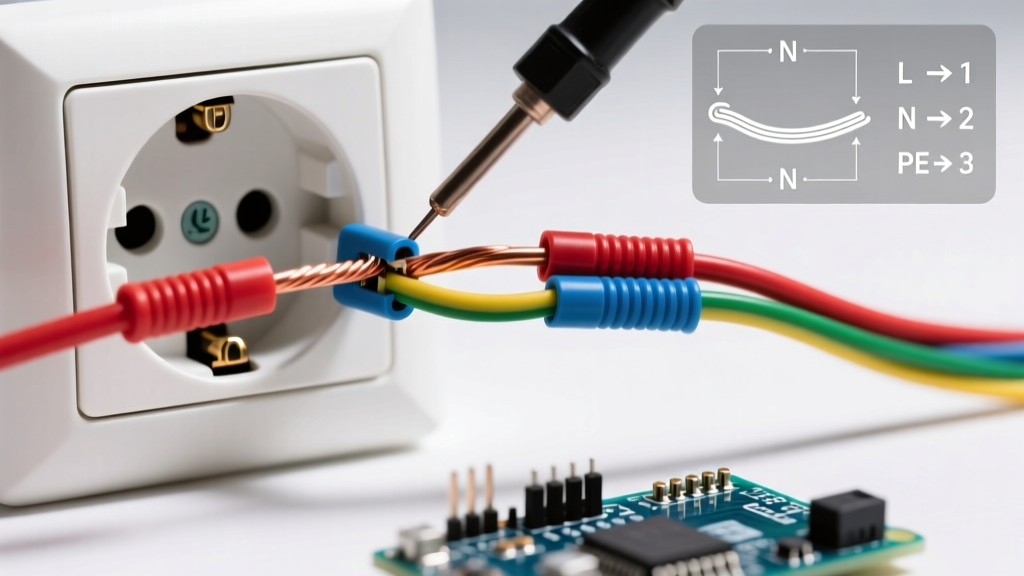
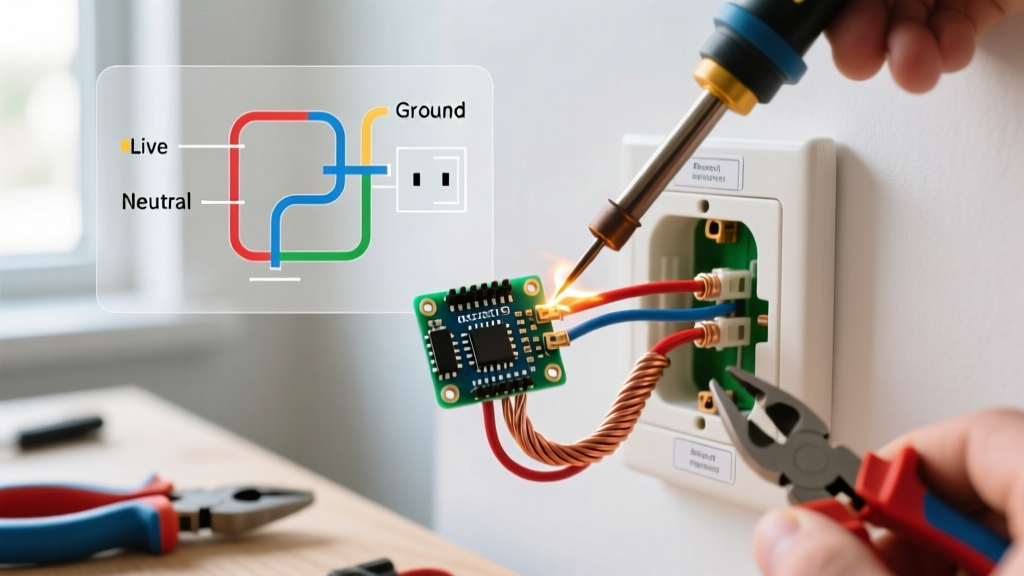
Form a "J-hook" at the end of your stripped wire using the nose of your linemans pliers. Hook the wire around the brass (hot) and silver (neutral) terminal screws in a clockwise direction. When you tighten the screw clockwise, the loop will naturally close and tighten around the screw shaft. If you loop it counter-clockwise, the screw will push the wire out from under the head as it tightens.
Expert Warning: Never Use "Backstab" Terminals
Budget receptacles feature push-in holes on the back. These rely on a tiny brass spring to grip the wire. Over years of thermal cycling (heating under load and cooling when idle), these springs lose tension, leading to high-resistance connections, arcing, and melted plastic. Always use the side-screw terminals or the "back-wire" clamp plates found on commercial-grade (spec-grade) receptacles.
Step 5: Calibrated Torque (The Missing Step)
As of recent NEC cycles, Article 110.14(D) requires that electrical connections be tightened to the manufacturer's specified torque. For a standard Leviton 15A receptacle, the brass and silver terminal screws require 14 inch-pounds of torque. Using a calibrated torque screwdriver ensures the wire is compressed enough to prevent arcing, but not so tight that it shears the screw head or damages the copper conductor.
Step 6: Fold and Mount
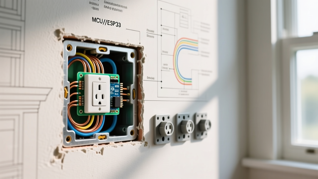
Carefully fold the wires into the back of the electrical box. Push the ground wire in first, followed by the neutrals (whites), and finally the hots (blacks). Mount the receptacle using the provided 6-32 mounting screws. Ensure the yoke (the metal strap) sits flush against the drywall or plaster ring to prevent the outlet from rocking when you plug in a cord.
Common Beginner Mistakes to Avoid
- Reverse Polarity: Swapping the hot and neutral wires. The hot (black) must always go to the brass screw, and the neutral (white) must always go to the silver screw. Reverse polarity leaves the appliance energized even when switched off.
- Breaking the Fin: Standard duplex outlets have a small metal break-off fin between the top and bottom brass screws. This allows one half of the outlet to be switched via a wall light switch while the other remains always-on. If your circuit does not require a split-wired setup, leave this fin intact. Breaking it accidentally will result in a dead top or bottom socket.
- Overcrowding the Box: NEC Article 314 dictates box fill calculations. If you are pigtailing multiple wires in a standard single-gang box, ensure you have adequate cubic inch capacity to prevent crushing the wires and damaging insulation.
Final Testing Protocol
Once the outlet is mounted and the faceplate is secured, restore power at the breaker panel. Do not simply plug in a lamp to test it. Use a dedicated receptacle tester (such as the Gardner Bender GRT-501). Plug it into the new outlet and read the LED matrix:
- Correct Wiring: Two yellow lights illuminated.
- Open Ground: Center yellow light only (Indicates the ground wire is disconnected).
- Hot/Neutral Reversed: Red and right-yellow light (Indicates reverse polarity; turn power back off and fix immediately).
By following these precise mechanical and electrical protocols, your DIY electric outlet install will match the safety, longevity, and code-compliance of a master electrician's work. Never compromise on termination torque or wire preparation; the integrity of your home's electrical system depends on the quality of every single connection.