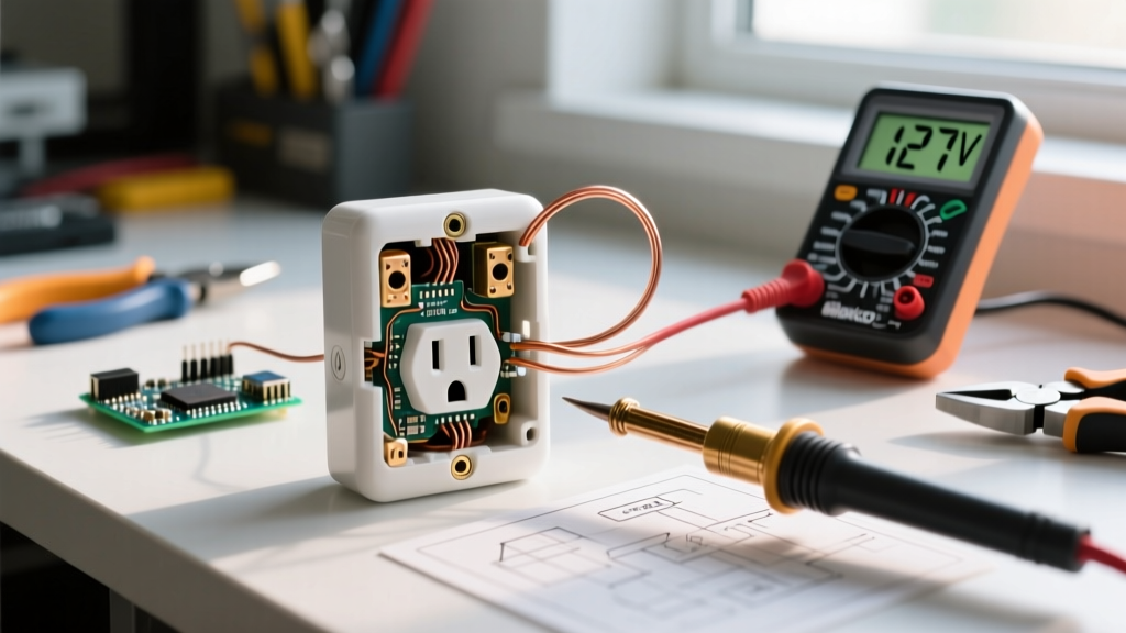

Pre-Replacement Diagnostic Inspection
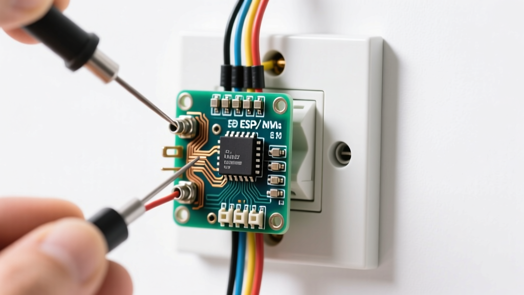
Learning how to change an electric outlet extends far beyond simply unscrewing a faceplate and swapping hardware. As a critical node in your home's electrical distribution system, a failing receptacle can harbor hidden thermal damage, degraded wire terminations, or compromised grounding paths. According to the National Fire Protection Association (NFPA), electrical distribution and lighting equipment are consistently among the leading causes of home structure fires. Before installing a new receptacle, a rigorous inspection of the existing junction box and wiring is mandatory.
When you remove the old outlet, inspect the thermoplastic yoke for signs of thermal runaway. Brown discoloration, melted nylon around the terminal screws, or a brittle, chalky texture indicates historical overheating. This is almost exclusively caused by high-resistance connections, typically from 'backstabbed' (push-in) wiring under heavy continuous loads like space heaters or window AC units.
The Receptacle Termination Failure Matrix
Understanding how the previous outlet was wired dictates how you must prepare the new one. Here is a breakdown of termination methods and their real-world failure rates:
| Termination Method | Wire Gauge Accepted | Failure Risk | 2026 NEC / UL Status |
|---|---|---|---|
| Push-In (Backstab) | 14 AWG Solid Only | High (Spring fatigue) | Permitted, but discouraged by pros |
| Side-Wire (Screw) | 14 & 12 AWG Solid | Low (If torqued properly) | Standard residential practice |
| Back-Clamp (Spec Grade) | 12 & 14 AWG Solid/Stranded | Very Low (Compression plate) | Commercial/High-end residential |
Essential Testing & Diagnostic Tools
Do not attempt this replacement with a basic $10 non-contact voltage pen alone. Professional inspection requires precise measurement. For a 2026-compliant toolkit, you need:
- CAT III True-RMS Multimeter: The Fluke 117 (approx. $245) is the industry standard for residential diagnostics, offering non-contact voltage detection and low-impedance testing to eliminate ghost voltages.
- Receptacle Tester with GFCI Trip: The Klein Tools RT210 ($32) verifies wiring polarity and tests ground fault protection trip times.
- Calibrated Torque Screwdriver: The Wiha 61100 ($85) ensures terminal screws are tightened to the exact UL 498 specification (typically 14 in-lbs), preventing cold-flow loosening over thermal cycles.
- Wire Strippers: Klein 11055 for precise 5/8-inch stripping without nicking the copper conductor.
Safe De-Energization & Verification Protocol
The Occupational Safety and Health Administration (OSHA) mandates strict verification protocols before touching any conductor. Follow this sequence to ensure the circuit is dead:
- Identify and Trip the Breaker: Turn off the corresponding 15A or 20A breaker at the main panel. If the panel is unlabeled, use a lamp or the RT210 to identify the correct circuit before switching it off.
- Initial NCVT Sweep: Use the non-contact voltage sensor on your multimeter to scan the faceplate and receptacle slots.
- The 3-Point Multimeter Test: Set your Fluke 117 to AC Voltage. Insert the probes into the receptacle to test three specific combinations:
- Hot to Neutral (Short slot to Long slot): Must read 0.0V.
- Hot to Ground (Short slot to Ground hole): Must read 0.0V.
- Neutral to Ground (Long slot to Ground hole): Must read 0.0V.
Expert Note: If Neutral-to-Ground reads any voltage above 0.2V while the breaker is off, you likely have a shared neutral from another active circuit. Stop and consult a licensed electrician.
Precision Termination: Step-by-Step Replacement
For standard 15A or 20A residential replacements in 2026, the Consumer Product Safety Commission (CPSC) and the NEC require Tamper-Resistant (TR) receptacles. We recommend the Leviton T5262-W (15A TR Duplex, approx. $3.85) or the Leviton T6262-W (20A TR Duplex, approx. $4.50).
1. Conductor Preparation
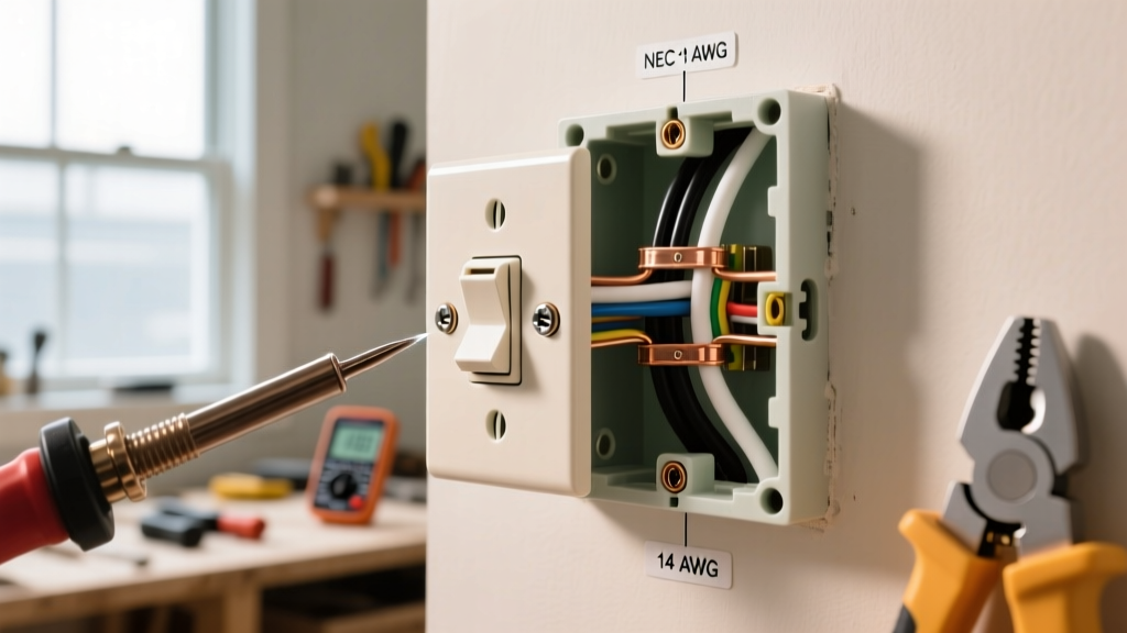
If the existing wires are damaged, frayed, or previously backstabbed and kinked, cut them back to fresh copper. Strip exactly 5/8-inch of insulation. Do not score the copper; a nicked wire creates a mechanical weak point that can snap under the terminal screw.
2. Forming the J-Hook
Using needle-nose pliers, bend the bare copper into a tight 'J-hook'. The hook must be sized so it wraps snugly around the terminal screw shaft, not resting on the threads.
3. Clockwise Termination
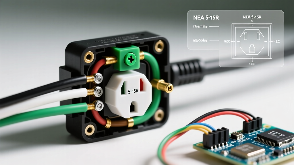
Loop the J-hook clockwise around the brass (hot) and silver (neutral) screws. This ensures that as you tighten the screw, the loop pulls tighter rather than splaying outward. Wrap the bare copper ground wire around the green grounding screw at the bottom of the yoke.
4. Torque Verification
Set your Wiha torque screwdriver to 14 in-lbs (1.58 Nm). Tighten each terminal screw until the driver clicks. This eliminates the guesswork and guarantees a gas-tight connection that will not arc under load.
Aluminum Wiring Warning: If your home was built between 1965 and 1972 and features solid aluminum branch wiring, standard copper-rated outlets are a severe fire hazard. You must use CO/ALR rated receptacles (like the Leviton 1209-W) and apply Noalox anti-oxidant compound to the conductors before termination.
Post-Installation Verification (The RT210 Test)
Once the outlet is secured to the box and the faceplate is installed, restore power at the panel. The final step in learning how to change an electric outlet properly is verifying the circuit's electrical geometry using the Klein RT210.
Insert the RT210 into the top receptacle. Observe the two amber and one red LED indicators:
- Correct Wiring: Left Amber ON, Right Amber ON, Red OFF. (This confirms proper hot/neutral polarity and a bonded ground path).
- Open Ground: Left Amber ON, Right Amber OFF, Red OFF. (The outlet lacks a ground connection; common in pre-1960s ungrounded circuits).
- Reversed Polarity: Left Amber OFF, Right Amber ON, Red OFF. (Hot and neutral are swapped; an immediate shock hazard).
- Hot/Ground Reversed: Left Amber OFF, Right Amber OFF, Red ON. (Critical fault; shut off breaker immediately).
Testing GFCI Protection
If the outlet is on a GFCI-protected circuit (required in kitchens, bathrooms, garages, and outdoors), press and hold the black 'TEST' button on the RT210. The receptacle should trip and cut power within 25 milliseconds at a 5mA fault current. If it does not trip, the upstream GFCI breaker or device has failed and must be replaced.
Common Edge Cases & Troubleshooting
Multivoltage Readings on Ghost Circuits
Sometimes, a multimeter will read 40V to 70V on a de-energized wire running parallel to a live wire in the same conduit. This is induced capacitive coupling (ghost voltage). Use the Lo-Z (Low Impedance) mode on the Fluke 117 to bleed off the phantom voltage and confirm the line is truly dead.
Box Fill Violations
If you are adding a GFCI receptacle or a smart outlet (like the Leviton DW15S), be aware of box fill capacities. GFCI devices are voluminous. A standard 14-cubic-inch shallow junction box may not physically accommodate the device and the required wire bending radius. If the wires are crushed against the back of the box, upgrade to a 22-cubic-inch deep box or use a box extender ring.
Frequently Asked Questions
Can I install a 20A outlet on a 15A breaker?
No. While you can install a 15A receptacle on a 20A circuit (as long as it's a duplex), the NEC strictly prohibits installing a 20A receptacle (identified by the T-slot neutral) on a 15A breaker. The breaker must match or exceed the receptacle's ampere rating to prevent the outlet from melting before the breaker trips.
Why does my new outlet spark when I plug in a vacuum?
A small blue spark upon insertion is normal for high-inductive loads like vacuums or power tools due to inrush current. However, if the spark is large, orange, or accompanied by a popping sound, the internal brass wipers of the receptacle may be defective, or the plug blades are damaged. Replace the plug head on the appliance immediately.
Do I need to pigtail the ground wire?
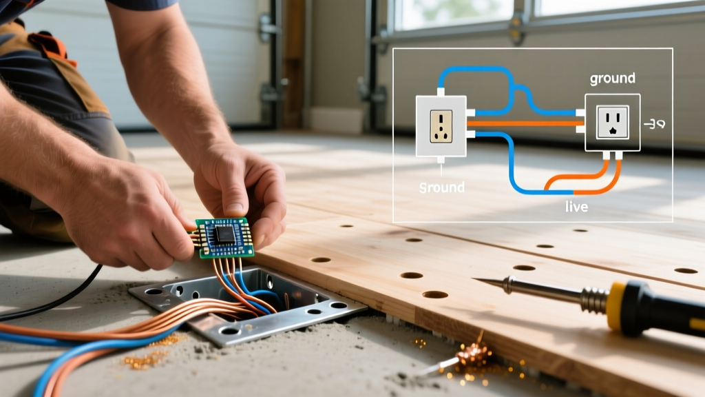
Yes. If you are installing multiple outlets in the same junction box, or if the metal box itself requires grounding, you must use a wire nut to pigtail the incoming and outgoing bare copper ground wires with a 6-inch lead running to the outlet's green screw. Never daisy-chain the ground through the outlet's yoke, as removing the outlet later would break the ground path for downstream devices.