
Decoding the Basic Electrical Outlet Wiring Diagram
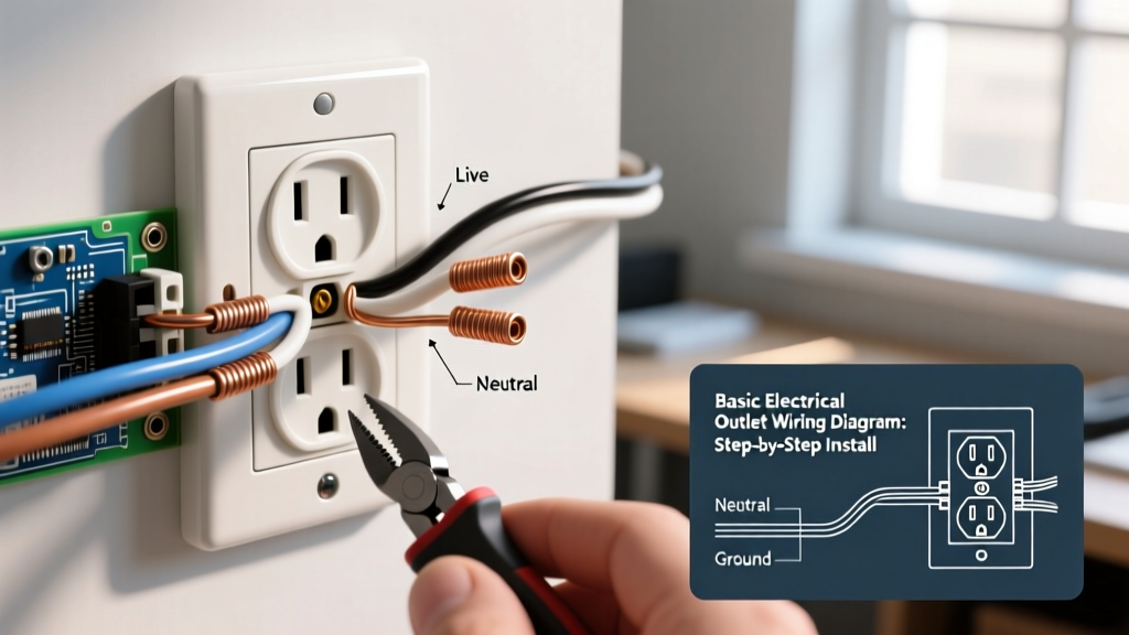
Understanding a basic electrical outlet wiring diagram is the foundational skill for any DIY electrical project. Whether you are replacing a damaged receptacle in a 1980s home or adding a new drop in a finished basement, the fundamental physics and code requirements remain consistent. A standard 120-volt duplex receptacle relies on three primary connections: the ungrounded conductor (hot), the grounded conductor (neutral), and the equipment grounding conductor (ground).
When you visualize the wiring diagram, picture the receptacle as a bridge between your home's electrical panel and the device you are plugging in. The National Fire Protection Association (NFPA 70), commonly known as the National Electrical Code (NEC), strictly dictates how these conductors must be terminated to prevent arc faults, thermal expansion failures, and shock hazards.
The Three Critical Terminals
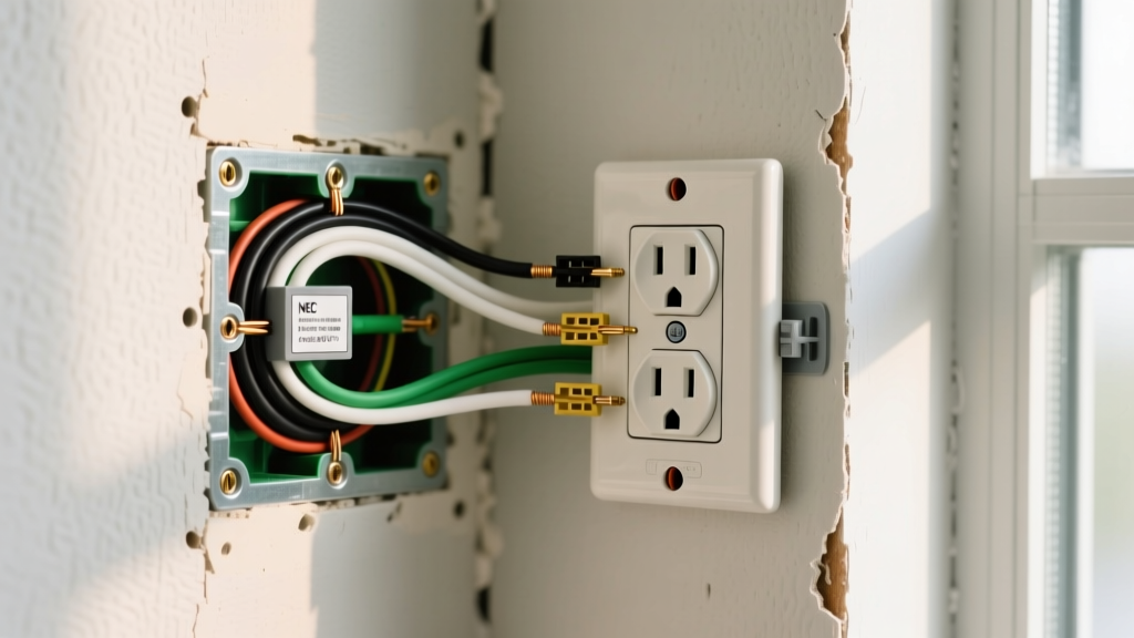
- Brass Screws (Hot/Line): Connects to the black (or red/blue) insulated wire. This carries the 120V alternating current from the breaker panel.
- Silver Screws (Neutral): Connects to the white (or gray) insulated wire. This completes the circuit, returning current to the panel.
- Green Screw (Ground): Connects to the bare copper or green insulated wire. This provides a safe path for fault currents, tripping the breaker if a short occurs.
Essential Tools and 2026 Material Costs
Before stripping a single wire, gather professional-grade tools. Relying on dull cutters or uncalibrated testers leads to nicked conductors and false voltage readings. Below is a realistic breakdown of what a professional-grade installation requires in 2026.
| Item / Tool | Recommended Specification | Avg. Cost (2026) |
|---|---|---|
| Tamper-Resistant (TR) Receptacle | Leviton 15A-125V Duplex (R52-05320-00W) | $1.85 - $2.50 |
| Wire Strippers | Klein Tools 11063W (10-20 AWG Solid/Stranded) | $28.00 |
| Torque Screwdriver | Klein Tools 70004 (10-75 in-lbs) | $85.00 |
| Non-Contact Voltage Tester | Fluke 2AC-II or Klein NCVT-3 | $35.00 |
| Wire Connectors | IDEAL Wire-Nut (Yellow #74B for 3x 14AWG) | $0.12 each |
Step-by-Step Installation Procedure
Follow this sequence meticulously. The U.S. Consumer Product Safety Commission (CPSC) reports that faulty receptacle wiring is a leading cause of residential electrical fires, often stemming from loose terminal connections rather than inherent component defects.
Step 1: Lockout, Tagout, and Verify
Navigate to your main service panel and switch off the breaker controlling the circuit. Apply a lockout tag to prevent accidental re-energizing. Remove the existing faceplate and receptacle. Insert your non-contact voltage tester into the slots and touch it to the side terminal screws. Never assume a wire is dead based solely on the breaker position; multi-wire branch circuits (MWBCs) can leave one half of a duplex receptacle energized.
Step 2: Cable Preparation and Stripping
Using your wire strippers, remove exactly 3/4 inch of insulation from the black, white, and ground wires. Crucial Edge Case: Do not score the copper conductor beneath the insulation. A nicked 14 AWG solid copper wire creates a structural weak point that will snap when folded into a crowded junction box, leading to an intermittent open-neutral fault.
Step 3: Forming the J-Hook
Use the needle-nose plier loop on your wire strippers to bend the exposed copper into a tight 'J' hook. The radius of the hook should perfectly match the radius of the terminal screw. This ensures maximum surface area contact between the wire and the brass/silver plate.
Step 4: Termination and Clock-Face Routing
Loop the wire around the terminal screw in a clockwise direction. As you tighten the screw, the clockwise rotation pulls the wire loop tighter under the screw head. Counter-clockwise routing will push the wire out as the screw turns. Ensure no bare copper is exposed outside the terminal plate (over-stripping), and ensure no insulation is trapped under the screw head (under-stripping).
Step 5: Torque to Specification
This is where amateurs fail. Hand-tightening is no longer acceptable under modern inspection standards. Set your torque screwdriver to the manufacturer's specification—typically 12 to 14 inch-pounds for standard 15A residential receptacles. Proper torque prevents thermal cycling from loosening the connection over a 5-to-10-year period.
Step 6: Grounding and Box Dressing
Connect the bare ground wire to the green screw. If you are working in a metal junction box, you must also run a 6-inch bare copper pigtail from the ground wire bundle to the metal box using a grounding clip or 10-32 ground screw. Carefully fold the wires in a 'Z' pattern (ground first, then neutral, then hot) to avoid pinching the insulation against the sharp metal edges of the box.
Critical Decision: Side-Wiring vs. Back-Wiring
Modern receptacles often feature push-in holes on the back. Understanding the difference between these termination methods is vital for long-term reliability.
| Method | Mechanism | Pros & Cons | Expert Verdict |
|---|---|---|---|
| Side-Wiring | Wire wrapped around terminal screw. | Pros: Visual inspection, high pull-out strength. Cons: Takes longer, requires torque tool. |
Industry Gold Standard |
| Push-In (Backstab) | Internal spring clamp grips solid wire. | Pros: Fast installation. Cons: Prone to thermal failure, cannot be reused. |
Avoid Completely |
| Clamp Back-Wire | Screw tightens a metal plate over wire. | Pros: Extremely secure, flat surface contact. Cons: Premium receptacles only ($4+). |
Best for Commercial |
NEC Code Note: Under NEC Article 406.12, all 15A and 20A receptacles installed in dwelling units must be Tamper-Resistant (TR). TR receptacles feature internal shutters that only open when equal pressure is applied to both slots simultaneously, preventing children from inserting foreign objects. Standard non-TR receptacles are strictly prohibited in residential living spaces as of the 2023 and 2026 code cycles.
Troubleshooting Edge Cases and Code Violations
Even with a perfect basic electrical outlet wiring diagram in mind, existing home wiring often presents hidden hazards. Watch for these specific failure modes:
1. Reversed Polarity
If the black (hot) wire is connected to the silver screw and the white (neutral) to the brass screw, the outlet will still power a lamp, but the internal switch of the appliance will only break the neutral path. This leaves the appliance's internal components energized at 120V even when turned off, posing a severe shock hazard during maintenance. Always verify with a plug-in circuit analyzer (e.g., Gardner Bender GRT-901) after installation.
2. The 'Bootleg' Ground
In older homes lacking a ground wire, some DIYers illegally jumper the neutral silver screw to the green ground screw to trick a receptacle tester into showing a 'correct' reading. This is incredibly dangerous. If the neutral wire ever disconnects upstream, the metal chassis of any plugged-in appliance will become fully energized at 120V. If no ground wire exists, you must install a GFCI receptacle and label it "No Equipment Ground" per NEC 406.4(D).
3. Overloaded 15A Circuits with 12 AWG Wire
While 12 AWG wire is rated for 20A, you can legally use it on a 15A breaker. However, wrapping thick 12 AWG solid copper around the small terminal screws of a standard 15A receptacle can result in poor contact or damaged screws. If your circuit uses 12 AWG wire, it is highly recommended to use a 20A-rated receptacle (which features a T-slot neutral) or a commercial-grade 15A receptacle designed with larger terminal plates to accommodate the thicker gauge.
Final Testing and Commissioning
Once the receptacle is secured to the box with its 6-32 mounting screws and the faceplate is installed, restore power at the breaker. Use a UL-listed receptacle tester to confirm correct wiring. The Underwriters Laboratories (UL) certification mark on your tester ensures it meets rigorous safety standards for voltage detection. A standard tester will display two yellow lights for a correctly wired outlet. If the red light illuminates, immediately cut power and reverse the hot and neutral connections. By adhering strictly to the diagram and utilizing proper torque specifications, your installation will remain safe, code-compliant, and reliable for decades.