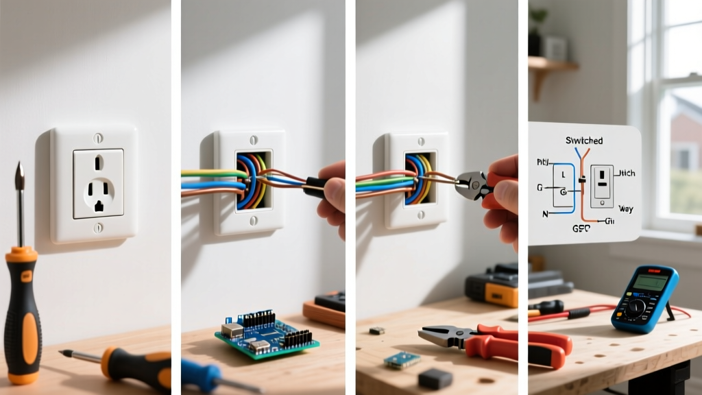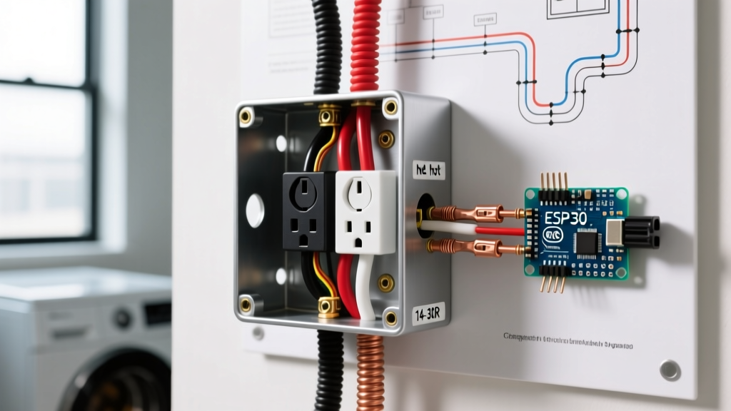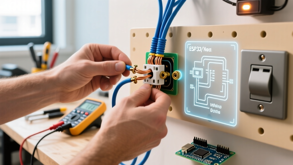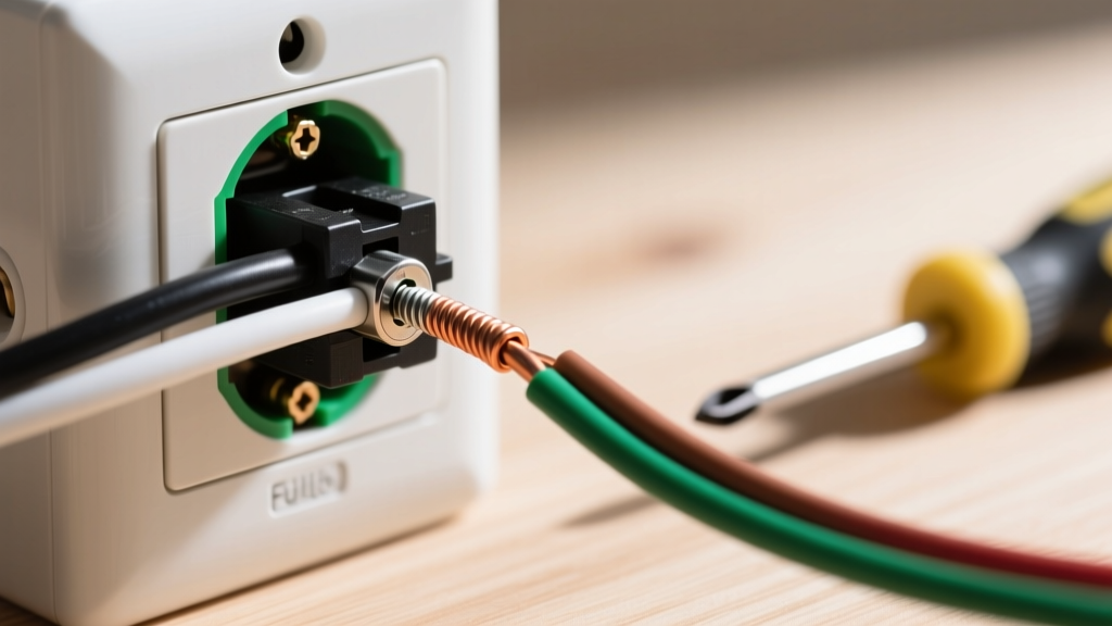

The Wiring Diagram Approach to Outlet Disconnection
Understanding how to disconnect electrical outlet wiring requires more than just a screwdriver; it demands a mental map of the branch circuit's topology. Whether you are replacing a damaged NEMA 5-15R duplex receptacle, upgrading to a 2026-compliant AFCI/GFCI model, or permanently decommissioning a wall box, treating the process as a reverse-engineering of a wiring diagram ensures both safety and code compliance. At ElectricalFlux, we approach every physical task through the lens of schematic logic. This guide breaks down the physical disconnection process by mapping it directly to standard electrical diagrams.
Safety Directive: According to the OSHA Electrical Safety Standards, working on energized circuits in residential settings without proper Lockout/Tagout (LOTO) procedures or verified dead-front testing is a leading cause of arc flash injuries. Always verify zero energy before touching a terminal.
Anatomy of a Standard 15A/20A Receptacle (NEMA 5-15R / 5-20R)
Before physically removing wires, you must visually map the terminals on the yoke. A standard duplex receptacle features three distinct termination zones, which correspond directly to your wiring diagram:
- Brass Terminals (Line/Hot): Accepts the black (or red) ungrounded conductor. This is the energized source from the breaker panel.
- Silver Terminals (Neutral): Accepts the white or gray grounded conductor. This completes the circuit back to the bus bar.
- Green Terminal (Ground): Accepts the bare copper or green insulated equipment grounding conductor (EGC).
Diagrammatic Note: Look closely at the brass side of the yoke. You will see a small metal connecting fin (tab) between the top and bottom brass screws. If this tab is intact, both outlets are on the same circuit. If it is broken, you are dealing with a split-receptacle (often a Multi-Wire Branch Circuit or a switched half-receptacle), which drastically changes your disconnection protocol.
Mandatory Tooling for Safe Disconnection
Do not rely on makeshift tools. Proper disconnection requires specific instruments to prevent damage to the conductors and ensure personal safety.
- Non-Contact Voltage Tester (NCVT): Fluke 1AC-II VoltAlert (approx. $35). Essential for initial field mapping before removing the faceplate.
- Contact Voltage Tester / Multimeter: Fluke 117 or a simple two-lead solenoid tester (Wiggy). Required to verify zero potential between Hot-Neutral and Hot-Ground.
- Insulated Screwdrivers: Klein Tools 32500 multi-bit stubby with 1000V rated insulation.
- Backstab Release Tool: A 1/8-inch flathead screwdriver or an IDEAL Super T-Stick to depress the release springs on push-in terminals.
Step-by-Step Disconnection Protocol
Follow this sequence to safely extract the receptacle from the gang box while maintaining the integrity of the branch circuit conductors.
Phase 1: Isolation and Verification
- Identify and Trip the Breaker: Locate the correct single-pole (or double-pole for MWBC) breaker in the load center and switch it to the OFF position.
- Verify Dead-Front: Insert your NCVT into the top and bottom slots of the receptacle. Next, use your two-lead tester. Place one probe in the short (Hot) slot and the other in the long (Neutral) slot. Confirm zero voltage. Repeat between Hot and the Ground U-slot.
Phase 2: Physical Extraction
- Remove the Yoke Screws: Remove the top and bottom 6-32 machine screws securing the receptacle yoke to the gang box. Support the device with your free hand so it does not snap the wires behind it.
- Extract and Inspect: Gently pull the receptacle out of the box. Immediately check for signs of thermal damage (melting, blackening, or a fishy odor), which indicates a high-resistance connection or loose termination.
Phase 3: Terminal Disconnection Sequence
While the circuit is dead, electrically the order of removal does not matter. However, building the muscle memory of a specific sequence prevents catastrophic errors when working on live-troubleshooting scenarios in commercial settings.
- Disconnect Ground First: Loosen the green screw and remove the bare copper wire.
- Disconnect Neutral Second: Loosen the silver screw(s) and remove the white wire(s).
- Disconnect Hot Last: Loosen the brass screw(s) and remove the black/red wire(s).
Wiring Configuration Matrix: Identifying Your Circuit Topology
When you pull the outlet from the box, the number and color of wires will immediately tell you where this outlet sits on your wiring diagram. Use this matrix to identify your configuration before fully detaching the wires.
| Configuration | Wires Present in Box | Diagram Identifier | Disconnection Complexity |
|---|---|---|---|
| End-of-Run | 1 Black, 1 White, 1 Ground | Single cable entering; final node on the schematic. | Low. Simply detach and cap if decommissioning. |
| Middle-of-Run (Daisy Chain) | 2 Black, 2 White, 2 Grounds | Two cables; device acts as a pass-through junction. | Medium. Must pigtail or reconnect downstream wires to maintain circuit continuity. |
| Split-Receptacle | 1 Black, 1 Red, 1 White, 1 Ground | Brass fin removed; top and bottom outlets on different breakers or one is switched. | High. Requires careful tagging to avoid cross-phasing upon reinstallation. |
| MWBC (Shared Neutral) | 1 Black, 1 Red, 1 White, 1 Ground | Two hots on separate phases sharing a single neutral return. | Critical. Requires 2-pole breaker shutoff to prevent lethal neutral shock. |
The MWBC Edge Case: A Lethal Diagramming Error
The most dangerous scenario when learning how to disconnect electrical outlet wiring is encountering a Multi-Wire Branch Circuit (MWBC) and failing to recognize it. In an MWBC, two hot wires (typically Black and Red) from opposite phases (e.g., Phase A and Phase B) share a single White neutral wire.
If you only turn off the breaker for the Black wire, the receptacle's brass fin might still be energized by the Red wire. Worse, if you disconnect the shared neutral while the Red wire's circuit is still active, the neutral wire you are holding will become energized at 120V, carrying the return current from the other phase. The NFPA 70 National Electrical Code (NEC) strictly requires MWBCs to be protected by a common-trip 2-pole breaker or handle-tied single-pole breakers (NEC 210.4) precisely to prevent this lethal edge case during maintenance.
Handling Push-In (Backstab) Connections
Many builder-grade receptacles installed between 1990 and 2020 utilize push-in backstab terminals rather than side-screw terminations. These spring-loaded connections are notorious for high-resistance failures over time due to thermal cycling.
How to release them: Do not simply pull and twist the wire, as this can strip the copper or break the spring mechanism inside the yoke. Locate the tiny rectangular release slot adjacent to the wire entry hole. Insert a 1/8-inch flathead screwdriver or a dedicated terminal release tool straight into the slot to depress the captive spring, then gently slide the wire out. If the wire is deeply scored or pitted from arcing, strip it back to fresh copper using a Klein Tools 11055 wire stripper before re-terminating it on a new device's screw terminals.
Proper Capping and Box Closure (NEC 314.29)
If your goal is to permanently disconnect and abandon the outlet, you cannot simply push the live wires back into the wall and cover them with a blank plate. The U.S. Consumer Product Safety Commission (CPSC) and the NEC mandate strict protocols for abandoned conductors.
- Capping: Every individual energized conductor must be capped with a UL-listed wire connector (e.g., IDEAL 341 Blue Wing-Nuts or Wago 221 2-conductor lever nuts). Do not bundle hots and neutrals together under a single wire nut.
- Grounding: The ground wires must remain bonded together and attached to the metal gang box (if applicable) using a green grounding screw or pigtail.
- Accessibility (NEC 314.29): Junction boxes containing spliced or capped live wires must remain permanently accessible. You may cover the box with a blank, solid cover plate secured by screws, but you may never drywall, plaster, or hide the box behind fixed cabinetry. If you wish to hide the box entirely, the conductors must be physically severed at their source and removed from the wall cavity.
Final Torque and Reinstallation Note
When reconnecting or transferring these wires to a new receptacle, the 2023/2026 NEC cycles heavily emphasize manufacturer torque specifications. While most residential 15A/20A receptacles do not explicitly print torque values on the yoke, industry standard dictates approximately 14 in-lbs for 14 AWG and 12 AWG copper on terminal screws. Using a calibrated torque screwdriver (like the Klein Tools 695) ensures the connection will not loosen under the thermal expansion and contraction of daily electrical loads, preventing future arc faults.