
The Diagnostic Power of Wiring Diagrams
When an electrical outlet failure occurs, most DIYers immediately reach for a plug-in receptacle tester. While these $15 tools can identify basic wiring errors, they fail to diagnose complex upstream faults, daisy-chain interruptions, or hidden thermal damage. To truly troubleshoot a dead or malfunctioning NEMA 5-15R receptacle, you must read the circuit through the lens of a wiring diagram. A wiring diagram is not just an installation map; it is a logical schematic that allows you to isolate variables, predict voltage drops, and safely trace faults from the breaker panel to the terminal screws.
According to the National Fire Protection Association (NFPA 70 National Electrical Code), improper wiring and loose connections remain leading causes of residential electrical fires. In 2026, with the widespread adoption of stringent AFCI/GFCI mandates, understanding how modern protection devices interact with legacy wiring diagrams is critical. This guide maps the most common outlet failure modes directly to their wiring diagram representations, providing actionable multimeter testing protocols for each.
CRITICAL SAFETY WARNING: Never perform physical terminal inspections or continuity testing without first verifying the circuit is de-energized at the breaker panel. Always use a Category III rated non-contact voltage tester (NCVT) and a True-RMS multimeter to confirm zero potential before touching bare conductors.Anatomy of a Standard 120V Receptacle Diagram
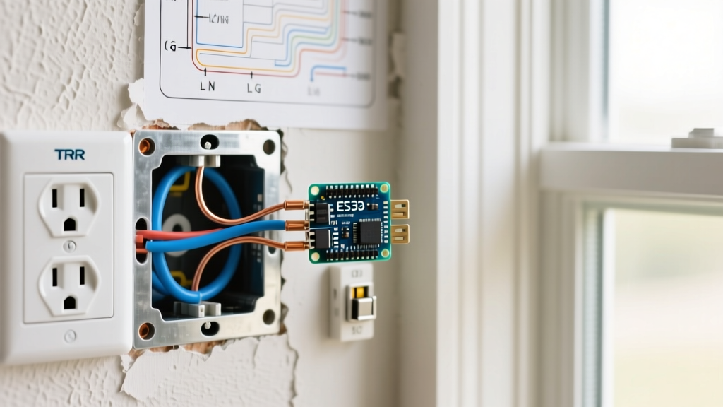
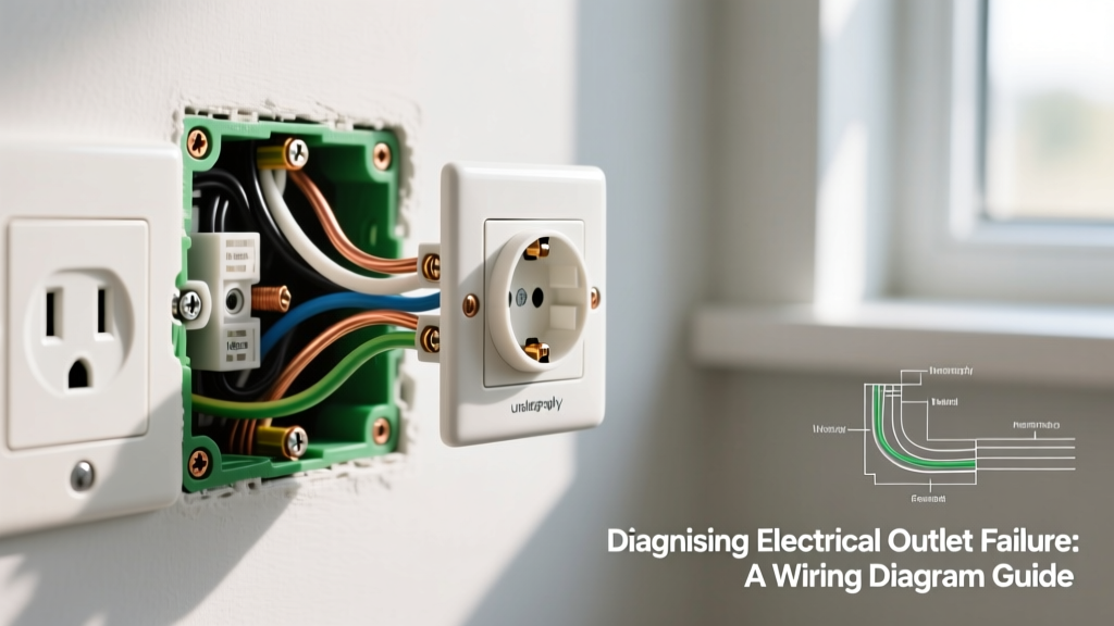
Before diagnosing a failure, you must understand the standard wiring diagram for a 15-amp, 125-volt duplex receptacle. The schematic relies on three primary conductors:
- Line (Hot): Typically black or red insulation. Connects to the brass-colored terminal screws. Carries 120V AC relative to ground.
- Neutral: White or gray insulation. Connects to the silver-colored terminal screws. Completes the circuit back to the panel's neutral bus bar.
- Equipment Grounding Conductor (EGC): Bare copper or green insulation. Connects to the green terminal screw. Provides a low-impedance fault path to trip the breaker.
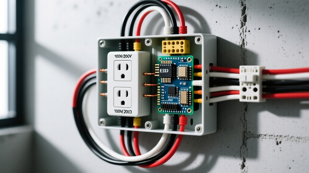
In a 'feed-through' or 'daisy-chain' diagram, the receptacle acts as a junction point. Incoming (line) wires connect to one set of terminals, while outgoing (load) wires connect to the second set, continuing the circuit to downstream outlets. Most electrical outlet failures in residential settings occur at these feed-through junction points due to mechanical stress or thermal cycling.
Top 4 Electrical Outlet Failure Modes Mapped to Diagrams
1. Open Neutral (The 'Phantom Voltage' Trap)
The Diagram Context: In a feed-through wiring diagram, the neutral wire from the upstream outlet passes through the silver terminal to feed the downstream outlet. If the upstream neutral connection fails (e.g., a backstabbed wire loses tension), the downstream circuit is broken.
The Failure Mode: You test the dead downstream outlet with a digital multimeter (DMM) and read 120V between Hot and Neutral. However, when you plug in a lamp, it doesn't turn on. This is 'phantom' or 'ghost' voltage, caused by capacitive coupling between the hot and disconnected neutral wires running parallel in the Romex cable.
Actionable Fix: Switch your multimeter to Low Impedance (LoZ) mode—standard on modern tools like the Fluke 117 ($220). LoZ mode inserts a low-impedance resistor into the test leads, draining ghost voltage. If the reading drops to 0V in LoZ mode, you have an open neutral. Trace the wiring diagram back to the previous physical outlet in the chain and inspect the silver terminal connections.
2. Bootleg Ground (The Deadly Shortcut)
The Diagram Context: A proper diagram shows the EGC originating from the panel's ground bus. In older ungrounded circuits (pre-1960s 2-wire NM cable), the ground wire is absent.
The Failure Mode: To pass a basic home inspection or trick a 3-prong tester, a previous worker may have installed a jumper wire between the neutral (silver) terminal and the ground (green) terminal on the receptacle. This is a 'bootleg ground.' If a neutral fault occurs upstream, the metal chassis of any plugged-in appliance becomes energized at 120V, posing a lethal shock hazard. The U.S. Consumer Product Safety Commission (CPSC) frequently cites improper grounding as a primary factor in appliance-related electrocutions.
Actionable Fix: A standard plug-in tester will show 'Correct' on a bootleg ground. To expose it, remove the receptacle cover and visually inspect for a jumper wire between the silver and green screws. If found, remove the jumper. Replace the receptacle with a GFCI outlet, which provides shock protection without requiring an equipment ground, and label it 'No Equipment Ground' per NEC Article 406.4(D).
3. Split-Receptacle Tab Error (Half-Switched Outlets)
The Diagram Context: In living rooms and bedrooms, wiring diagrams often feature a 'split-wired' receptacle. The top half is fed by an always-hot circuit, while the bottom half is fed by a switched-hot circuit (controlled by a wall switch). This is achieved by snapping off the small brass connecting fin (tab) on the hot side of the receptacle.
The Failure Mode: When replacing a damaged split-wired outlet, a DIYer installs a standard receptacle but forgets to break the brass tab. When the wall switch is turned on, it sends 120V down the switched leg directly into the always-hot leg, creating a dead short. This results in a massive spark, immediate breaker trip, and potentially melted wire insulation at the wire nut junction in the switch box.
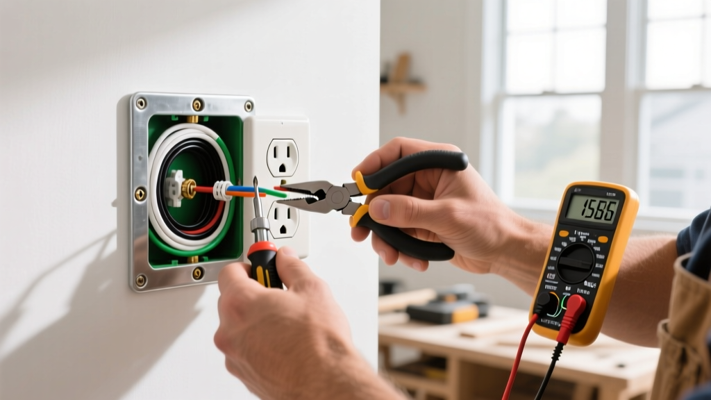
Actionable Fix: Always photograph the existing outlet's fin configuration before removal. If replacing a split receptacle, use needle-nose pliers to twist and snap the brass tab on the hot side only. Never break the silver (neutral) tab unless the specific schematic explicitly calls for a multi-wire branch circuit (MWBC) with two separate neutral returns, which is rare in modern residential wiring.
4. Backstab Connection Thermal Failure
The Diagram Context: Wiring diagrams specify termination at the terminal screws, where the wire is wrapped clockwise around the brass or silver post and torqued down.
The Failure Mode: Receptacles feature 'push-in' (backstab) holes on the rear for speed. These rely on a small internal brass spring clip to grip 14 AWG wire. Over years of thermal expansion and contraction (from plugging in high-draw devices like space heaters or vacuums), the spring clip loses tension. The connection develops high resistance, generating immense heat that melts the plastic housing and causes voltage drops or arcing.
Actionable Fix: Commercial-grade receptacles (like the Leviton 5362 or Eaton TRCR15W, typically $4 to $7 each) have largely eliminated backstab holes in favor of side-wire or screw-terminal-only designs. When replacing a failed outlet, always use the screw terminals or the internal pressure plates (if equipped), torquing to the manufacturer's specification (usually 12-14 in-lbs).
Diagnostic Matrix: Multimeter Readings vs. Wiring Faults
Use this matrix in conjunction with your True-RMS multimeter to rapidly identify the specific failure mode based on voltage readings at the dead receptacle.
| Measured Voltage (H-N) | Measured Voltage (H-G) | Measured Voltage (N-G) | Probable Wiring Diagram Fault |
|---|---|---|---|
| 0V | 120V | 120V | Open Neutral (Upstream feed-through failure) |
| 120V | 0V | 120V | Open Ground or Bootleg Ground masking a fault |
| 120V | 120V | 0V | Normal Operation (No fault) |
| 0V | 0V | 0V | Open Hot (Tripped breaker, broken wire, or tripped upstream GFCI) |
| 60V - 90V | 120V | 30V - 60V | High-Resistance Neutral or Loose Hot Connection (Voltage Drop) |
Step-by-Step Trace: Following the Diagram from Panel to Receptacle
When the matrix indicates an 'Open Hot' (0V across all combinations), the failure is upstream. Follow this tracing protocol:
- Verify the Breaker: Ensure the correct breaker in the panel is fully in the 'ON' position. If it is an AFCI/GFCI breaker, check for a tripped indicator flag on the breaker itself.
- Locate the First-in-Chain Receptacle: Identify the outlet physically closest to the panel on that circuit. This is the first node on your wiring diagram.
- Inspect Upstream GFCIs: The Electrical Safety Foundation International (ESFI) notes that many homeowners are unaware that standard outlets in living rooms or bedrooms may be protected by a GFCI receptacle located in a bathroom, garage, or exterior wall. A tripped upstream GFCI will cut power to all downstream standard outlets.
- Check Wire Nuts in Junction Boxes: If the first receptacle has power on the line side but not the load side, the failure is at the wire nut splice. Remove the wire nuts, strip back any oxidized copper, and reconnect using a fresh twist-on connector or a push-in wire connector (like Wago 221 series).
Modern Code Revisions: GFCI and AFCI Wiring Integration
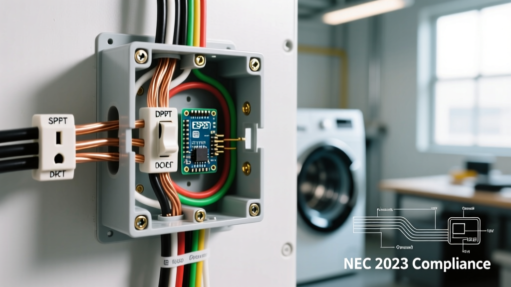
As local jurisdictions continue to adopt the 2023 NEC (which heavily influences 2026 building standards), the wiring diagrams for residential outlets have become more complex. Almost all 125V, 15A, and 20A receptacles in dwelling units now require both AFCI (branch circuit protection) and GFCI (point-of-use protection).
When replacing a failed standard outlet with a GFCI receptacle, the wiring diagram changes significantly. You must differentiate between the LINE terminals (incoming power from the panel) and the LOAD terminals (outgoing power to protect downstream outlets). Connecting the incoming hot and neutral to the LOAD terminals is a common failure mode; the GFCI will power its own receptacle but will fail to reset or provide downstream protection, and the test button will not function correctly. Always use the included tape or a multimeter to identify the line conductors before connecting them to the GFCI's line terminals.
Frequently Asked Questions
Why does my outlet spark when I plug in a vacuum?
A small blue spark is normal inductive arcing when a high-draw motor is plugged in while the device's switch is in the 'ON' position. However, a loud pop, orange spark, or melted plastic indicates a loose internal terminal connection or a failing backstab wire that requires immediate replacement.
Can I use a 20-amp receptacle on a 15-amp breaker?
No. NEC Article 210.21(B)(3) dictates that a 15-amp circuit can only utilize 15-amp receptacles. Installing a 20-amp (NEMA 5-20R) receptacle on a 15-amp breaker misleads users into plugging in high-draw equipment that the 14 AWG circuit wire cannot safely handle, risking thermal failure and fire.
What causes an outlet to feel warm to the touch?
A warm faceplate indicates high electrical resistance at the terminal connections. This is often caused by backstabbed wires, under-torqued screw terminals, or aluminum wiring oxidizing at copper terminals. Turn off the breaker immediately and replace the receptacle using screw-terminal terminations.
Conclusion
Diagnosing an electrical outlet failure requires moving beyond simple plug-in testers and learning to read the circuit's wiring diagram. By understanding feed-through topologies, recognizing the dangers of bootleg grounds, and utilizing a True-RMS multimeter to differentiate between phantom voltage and true open neutrals, you can safely and accurately restore power to your home's circuits. Always prioritize terminal screw connections over push-in backstabs, and ensure your repairs align with current NEC AFCI and GFCI mandates for maximum safety.