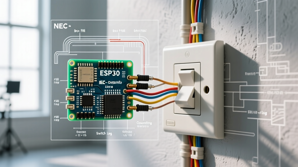

The Blueprint of Electrical Safety and Code Compliance
Interpreting electrical switch wiring diagrams is often viewed merely as a roadmap to make a light turn on. However, from a professional and safety standpoint, these diagrams are critical compliance documents. A correctly drawn diagram ensures that your installation meets the rigorous standards of the National Electrical Code (NEC), preventing overheating, arc faults, and catastrophic electrical fires. As jurisdictions across the country adopt the 2023 and upcoming 2026 NEC cycles, the margin for error in switch wiring has effectively dropped to zero.
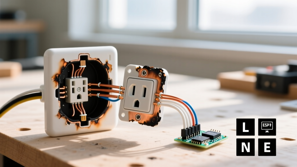
According to the National Fire Protection Association (NFPA), electrical failures or malfunctions account for tens of thousands of home structure fires annually. Misinterpreting a wiring diagram—specifically confusing line and load conductors or ignoring box fill capacities—is a primary culprit in residential electrical hazards. This guide dissects the anatomy of switch wiring diagrams through the lens of strict NEC code compliance, ensuring your 2026 installations are both functional and legally sound.
Decoding Standard Switch Diagram Symbology
Before pulling a single wire, you must fluently read the schematic symbols presented in electrical switch wiring diagrams. Standardized by the National Electrical Manufacturers Association (NEMA), these symbols dictate the flow of current and the physical routing of conductors.
- Line (Source): Typically represented by a solid line entering the switch box from the breaker panel. This carries the continuous 120V (or 240V) potential.
- Load: The conductor exiting the switch to the fixture. In diagrams, this is often shown with a broken line or an arrow pointing toward the luminaire symbol.
- Travelers: In 3-way and 4-way diagrams, travelers are depicted as parallel lines connecting the brass terminals of multiple switches. They carry the switched hot between locations.
- Neutral (Grounded Conductor): Shown as a white wire bypassing the switch and connecting directly to the load. Crucial 2026 Note: Modern diagrams must now show the neutral pigtailing to the switch itself to accommodate smart switches and timers per NEC 404.2(C).
- Equipment Grounding Conductor (EGC): Depicted as a green or bare wire connecting to the green grounding screw on the switch yoke and the metal box (if applicable).
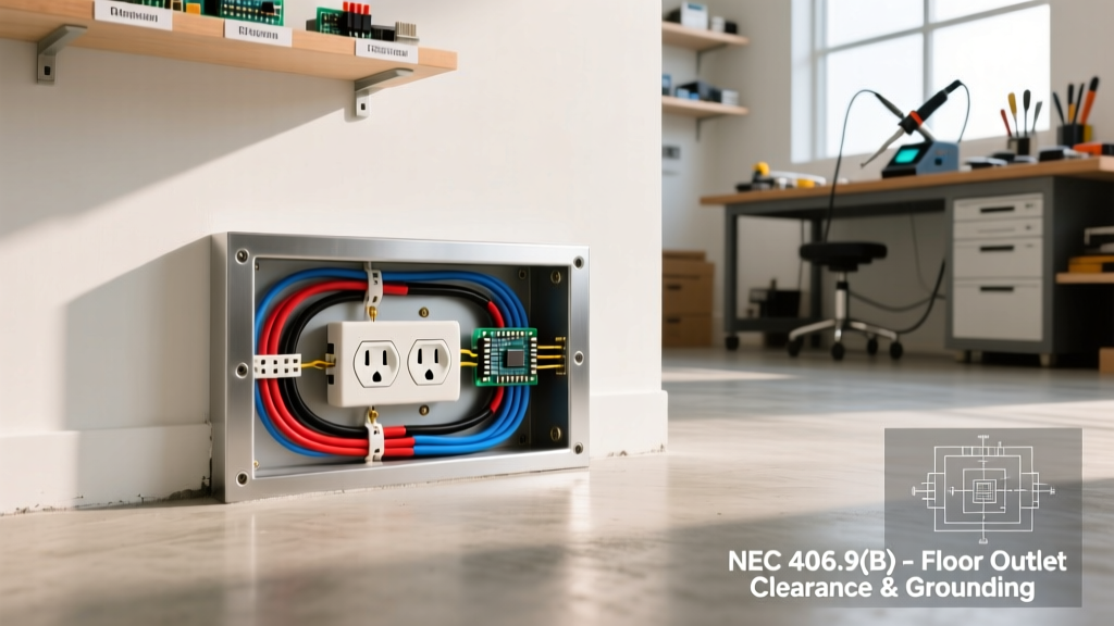
Code Alert: NEC Article 404.9(B) mandates that snap switches must be effectively grounded. If your diagram shows a switch without a dedicated ground connection to the box or yoke, the diagram is inherently non-compliant for modern installations, regardless of the switch type.
NEC Code Compliance Matrix for Switch Wiring
When reviewing electrical switch wiring diagrams, cross-reference the layout with the following NEC articles to ensure the schematic meets current safety mandates.
| NEC Article | Code Requirement | Diagram Verification Point |
|---|---|---|
| 404.2(A) | Switches must disconnect the ungrounded (hot) conductor, never the neutral. | Ensure the white wire is not routed through the switch terminals unless specifically marked as a re-identified hot (e.g., with black tape). |
| 404.2(C) | Neutral conductors must be present at all switch locations controlling lighting. | Verify the diagram shows a neutral wire entering the switch box and capping off or pigtailing to smart switches. |
| 210.12 | AFCI protection is required for all 120V, 15A/20A branch circuits supplying outlets in dwelling unit bedrooms, living rooms, etc. | If the diagram features a standard breaker, ensure it is an AFCI type, or that the switch itself is an AFCI-combo device (rare but permissible). |
| 314.16 | Box fill calculations must not exceed the cubic inch capacity of the enclosure. | Count all conductors, clamps, and devices in the diagram to verify the specified box size (e.g., 18 cu in for standard 12 AWG single-gang). |
For deeper insights into branch circuit requirements and grounding methodologies, the Occupational Safety and Health Administration (OSHA) provides extensive guidelines on electrical safety practices that align with NEC mandates, emphasizing the lethal risks of improper neutral switching.
The Hidden Metric: Box Fill Calculations in Diagrams
A common failure in amateur electrical switch wiring diagrams is the omission of box fill constraints. A diagram might show three 14/2 NM cables entering a standard 12-cubic-inch single-gang 'old work' box to feed a 3-way switch. While electrically functional, this is a severe NEC violation.
Calculating Box Fill (NEC 314.16)
To ensure your diagram translates to a safe physical installation, apply the following volume allowances per conductor based on wire gauge:
- 14 AWG Wire: 2.0 cubic inches per conductor.
- 12 AWG Wire: 2.25 cubic inches per conductor.
- 10 AWG Wire: 2.5 cubic inches per conductor.
Example Calculation for a 12 AWG 3-Way Switch Box:
Imagine a diagram showing two 12/2 cables and one 12/3 cable entering a box with a single 3-way switch.
- Conductors: 2 (from first 12/2) + 2 (from second 12/2) + 3 (from 12/3) = 7 current-carrying conductors. (7 x 2.25 = 15.75 cu in).
- Equipment Grounds: All bare/green wires count as 1 volume allowance. (1 x 2.25 = 2.25 cu in).
- Clamps: Internal cable clamps count as 1 volume. (1 x 2.25 = 2.25 cu in).
- Device (Switch): The switch counts as 2 volume allowances based on the largest wire. (2 x 2.25 = 4.5 cu in).
- Total Required Volume: 15.75 + 2.25 + 2.25 + 4.5 = 24.75 cubic inches.
If your diagram specifies a standard 18 cu in single-gang box for this scenario, the design is flawed and will result in crushed wires, damaged insulation, and a failed inspection. You must upgrade the diagram to specify a deep single-gang box (22-24 cu in) or a double-gang mud ring.
Advanced Configurations: 3-Way and Smart Switch Integrations
Standard single-pole diagrams are straightforward, but 3-way and smart switch diagrams introduce complex variables that demand strict adherence to manufacturer specs and code.
3-Way Switch Traveler Identification
When wiring a standard 3-way circuit using a reliable model like the Leviton Decora 5603 (retailing around $4.50), the diagram must clearly distinguish the 'Common' terminal from the 'Traveler' terminals. The common terminal (identified by a black or dark-colored screw) must connect to the line source on the first switch and the load on the second switch. The travelers (brass screws) connect to each other. Reversing the line and travelers will result in a circuit that functions erratically and can create a shock hazard at the fixture during bulb replacement.
The Smart Switch Neutral Mandate
Upgrading to smart lighting is a major trend in 2026. However, installing a smart switch like the Lutron Caseta PD-5S-DV ($65.00) or similar Wi-Fi/Z-Wave alternatives requires a neutral wire to power the internal radio and microcontroller. Older electrical switch wiring diagrams (pre-2011 NEC) often omitted the neutral at the switch loop. If your existing physical wiring lacks a neutral, you cannot legally or safely use a standard smart switch. You must either pull a new neutral conductor or utilize a specific no-neutral smart switch (like the Lutron Caseta PD-6ANS) which utilizes a proprietary bypass module installed at the fixture to prevent ghosting and flickering on low-wattage LED bulbs.
Common Wiring Diagram Misinterpretations & Failure Modes
Even with a perfect diagram, field execution can introduce critical failures. Be vigilant against these specific edge cases:
- The 'Bootleg' Ground: A diagram might show a ground wire connecting to the neutral bus in a subpanel, or a jumper wire between the neutral and ground screw on a receptacle/switch combo. This is a lethal NEC violation. If a neutral fault occurs, the switch yoke becomes energized at 120V.
- Shared Neutrals on Multi-Wire Branch Circuits (MWBC): If your diagram shows two hot wires (black and red) from different phases sharing a single white neutral wire to feed two separate switches, NEC 210.4(B) requires a simultaneous disconnect mechanism (a 2-pole breaker or handle-tied single-pole breakers). Failing to include this in the diagram risks overloading the shared neutral and electrocuting an electrician who turns off only one breaker.
- Reversed Line/Load on AFCI/GFCI Devices: When a diagram specifies an AFCI/GFCI combo switch or receptacle, the line and load must be exact. Reversing them allows the device to function and reset, but it strips the downstream protection, leaving the circuit vulnerable to arc faults while giving a false sense of security.
Frequently Asked Questions (FAQ)
Can I use a 14 AWG wire on a 20A breaker if the diagram allows it?
No. NEC Article 240.4(D) strictly limits 14 AWG copper to 15A overcurrent protection. Even if an electrical switch wiring diagram incorrectly pairs 14 AWG with a 20A breaker, the NEC overrides the schematic. Always use 12 AWG for 20A circuits.
Do I need to ground a plastic switch box?
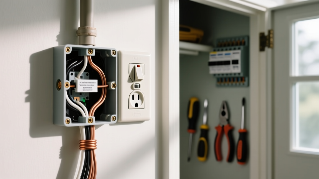
Nonmetallic (plastic) boxes do not require a grounding connection to the box itself. However, NEC 404.9(B) still requires the equipment grounding conductor to be connected to the switch's green grounding screw. The diagram should show the ground wire bypassing the plastic box and terminating directly on the device.
Where can I find verified, code-compliant switch diagrams?
Always refer to the manufacturer's installation sheets included with the hardware, or consult authoritative industry resources like EC&M (Electrical Construction & Maintenance) for updated code interpretations and verified schematic examples.
Final Thoughts on Diagram Literacy
Mastering electrical switch wiring diagrams is not just about connecting point A to point B; it is about translating a 2D schematic into a 3D, code-compliant, and thermally safe physical reality. By rigorously checking box fill, enforcing the neutral mandate, and respecting NEC grounding articles, you ensure that every switch you wire in 2026 and beyond operates safely for decades to come.