
The Fundamentals of a Safe Electrical Outlet Hookup
Performing a standard 120V electrical outlet hookup is a rite of passage for home DIYers. Whether you are replacing a damaged receptacle in a living room or wiring a new addition, understanding the mechanics of a standard 15-amp duplex outlet is essential. However, because this is the most common electrical task, it is also the most frequently botched, leading to loose connections, arcing, and residential fires.
In this comprehensive beginner tutorial, we will walk through the exact procedures, tool requirements, and 2026 National Electrical Code (NEC) considerations necessary to execute a flawless and safe electrical outlet hookup. We will focus on the standard 15-amp, 120-volt receptacle, which powers the vast majority of general-purpose household circuits.
Safety Warning: According to the Electrical Safety Foundation International (ESFI), electrical receptacles and wiring are involved in thousands of home structure fires annually. Never bypass power verification steps, and always treat every wire as live until proven otherwise with a calibrated tester.
15-Amp vs. 20-Amp Receptacles: Know Your Circuit
Before touching a screwdriver, you must identify the circuit's amperage. Installing a 20-amp receptacle on a 15-amp circuit is a code violation, and while installing a 15-amp receptacle on a 20-amp circuit is technically permitted by the NEC under specific multi-outlet branch circuit rules, it is best practice to match the receptacle rating to the breaker and wire gauge.
| Feature | 15-Amp Receptacle | 20-Amp Receptacle |
|---|---|---|
| Breaker Size | 15 Amp | 20 Amp |
| Wire Gauge Required | 14 AWG (or 12 AWG) | 12 AWG (or 10 AWG) |
| Neutral Slot Shape | Two parallel vertical slots | One vertical, one horizontal (T-shape) |
| Typical Cost (2026) | $2.00 - $3.50 | $3.50 - $6.00 |
| Common Applications | Bedrooms, living rooms, hallways | Kitchens, garages, workshops, bathrooms |
Essential Tools for a Professional-Grade Installation
Skip the cheap hardware store multi-tools. A reliable electrical outlet hookup requires precision instruments to ensure secure terminations and personal safety. Budget approximately $75 to $90 for these foundational tools if you do not already own them:
- Non-Contact Voltage Tester: Fluke 1AC-II VoltAlert (~$38). Do not rely on cheap, unbranded testers that can yield false negatives.
- Wire Strippers: Klein Tools 11057 (14-10 AWG) (~$28). Features precise stripping holes that prevent nicking the copper conductor.
- Receptacle: Leviton Decora 15A Tamper-Resistant (Model R52-05320-00W) (~$2.50). Features side-wire terminal plates for superior grip.
- Receptacle Tester: Gardner Bender GRT-500 (~$12). Essential for verifying polarity and ground post-installation.
- Insulated Screwdrivers: Wiha 1000V insulated Phillips #2 and 5/16" Slotted (~$25).
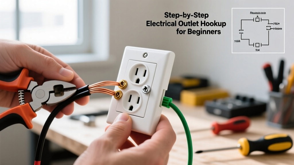
Step-by-Step Electrical Outlet Hookup Tutorial
Step 1: Lockout, Tagout, and Verify
Head to your main electrical panel and switch off the breaker controlling the outlet. To align with OSHA's Lockout/Tagout guidelines, place a piece of tape over the breaker or use a physical breaker lockout device so no one accidentally flips it back on while you are working. Return to the outlet, insert your Fluke non-contact voltage tester into both the top and bottom slots of the receptacle. The tester must remain completely silent and unlit. Finally, remove the faceplate and test the exposed wires directly.
Step 2: Extract and Prep the NM-B Cable
Unscrew the old receptacle and gently pull it out of the gang box. You should have about 6 to 8 inches of slack extending past the front edge of the box. If the existing wires are brittle, heavily oxidized, or damaged from previous backstabbing, you must cut them back to fresh copper and strip new ends. Ensure the outer yellow or white NM-B (Romex) sheath extends into the box by at least 1/4 inch, as required by the NEC. The sheath should never be stripped all the way back to the cable clamp.
Step 3: Precision Wire Stripping
Using your Klein Tools 11057 strippers, strip exactly 1/2 inch (12.7mm) of insulation from the black (hot) and white (neutral) wires. Most modern Leviton and Eaton receptacles feature a physical "strip gauge" molded into the back of the plastic yoke. Match your stripped copper length to this gauge.
Pro Tip: If you expose too much copper, you risk a short circuit when the outlet is pushed back into the box. If you expose too little, the insulation will get caught under the terminal screw, resulting in a high-resistance connection that will generate heat and eventually fail.
Step 4: The Side-Wiring Technique (Never Backstab)
This is where most beginners make a critical error. Modern receptacles have "quick wire" push-in holes on the back. Do not use them. Backstabbed connections rely on a tiny internal metal spring that grips the wire. Over time, thermal expansion and contraction cause these springs to loosen, leading to arcing and melted plastic.
Instead, use the side terminal screws:
- Ground (Bare Copper): Connect to the green screw at the bottom. Loop the wire clockwise around the screw.
- Neutral (White): Connect to the silver screw. Loop clockwise.
- Hot (Black): Connect to the brass screw. Loop clockwise.
Why clockwise? When you tighten the screw (turning it clockwise), the loop naturally tightens around the shaft. If you loop it counter-clockwise, tightening the screw will push the wire loop out from under the head.
Tighten the screws firmly until the terminal plate clamps down completely on the wire. While the 2026 NEC cycle heavily emphasizes torque screwdrivers for breaker terminations, standard 15A residential receptacle screws typically require about 12 to 14 inch-pounds of torque. Tighten until snug and give a gentle tug on the wire to ensure it is locked in place.
Step 5: The Z-Fold and Securing
Carefully fold the wires back into the gang box. Do not just shove the outlet in, as this can pinch the ground wire against the metal box or loosen the hot terminal. Use the "Z-fold" method: fold the ground wire flat against the back of the box, fold the neutral wire in a Z-shape behind the outlet, and let the hot wire fold naturally to the side. Align the outlet yoke with the box ears, insert the 6-32 mounting screws, and tighten evenly to keep the receptacle level.
2026 NEC Code Requirements to Keep in Mind
The National Fire Protection Association (NFPA) updates the NEC every three years. When performing an electrical outlet hookup in 2026, you must adhere to the following modern mandates:
- Tamper-Resistant (TR) Receptacles: Under NEC Article 406.12, all 15A and 20A, 125V and 250V receptacles installed in dwelling units must be tamper-resistant. These feature internal shutters that only open when equal pressure is applied to both slots simultaneously, preventing children from inserting foreign objects.
- AFCI and GFCI Protection: Depending on the room, your outlet may require Arc-Fault Circuit Interrupter (AFCI) protection (required in almost all living spaces) or Ground-Fault Circuit Interrupter (GFCI) protection (required in wet locations like kitchens, bathrooms, garages, and outdoors). If you are replacing an existing standard outlet in a kitchen, you must upgrade it to a GFCI receptacle or ensure the breaker provides GFCI protection.
Common Beginner Mistakes & Troubleshooting
After turning the breaker back on, plug in your Gardner Bender receptacle tester. Here is how to read the results and fix common errors:
- Open Ground (Yellow/Red/Yellow light pattern): The bare copper wire is not making solid contact with the green screw, or the grounding path back to the panel is broken. Turn the power off and re-terminate the ground wire.
- Reverse Polarity (Red/Yellow light pattern): You swapped the hot and neutral wires. The black wire must be on the brass screw, and the white wire must be on the silver screw. This is a severe shock hazard because the internal switch of a plugged-in appliance will interrupt the neutral instead of the hot, leaving the appliance energized even when turned off.
- Hot/Ground Reverse: This usually indicates a "bootleg ground," where a previous DIYer connected the neutral wire to both the silver and green screws to fake a ground reading. This is incredibly dangerous and must be corrected immediately.
Final Thoughts
A successful electrical outlet hookup relies on patience, precision, and a refusal to take shortcuts. By avoiding backstab terminals, stripping wires to the exact millimeter, and verifying your work with a dedicated tester, you ensure that your home's electrical system remains safe and reliable for decades. Always respect the power of the grid, and when in doubt, consult a licensed master electrician.