
Beyond the Basics: Why the Definition of Electrical Outlet Matters for Troubleshooting
Most DIYers and even some junior electricians use the terms "outlet" and "receptacle" interchangeably. However, when you are diagnosing a dead circuit, a melted faceplate, or a nuisance-tripping breaker, understanding the strict definition of electrical outlet according to the National Electrical Code (NEC) fundamentally changes how you isolate faults. A misunderstanding of these terms can lead you to test the wrong junction box, misinterpret voltage drop readings, or miss a critical code violation hidden inside the wall.
In this comprehensive diagnostic guide, we will break down the exact NEC definitions, dissect the internal anatomy of modern 15A and 20A duplex receptacles, and provide a professional-grade troubleshooting matrix using True RMS multimeters to identify hidden failure modes.
The NEC Definition of Electrical Outlet vs. Receptacle
According to NFPA 70: National Electrical Code (NEC) Article 100, the definitions are distinctly separate:
- Outlet: "A point on the wiring system at which current is taken and supplied utilization equipment."
- Receptacle: "A contact device installed at the outlet for the connection of an attachment plug."
Troubleshooter's Insight: A hardwired smoke detector, a ceiling fan junction box, and a standard wall plug are all outlets. However, only the wall plug is a receptacle. If a homeowner reports a "dead outlet in the bedroom," and you only test the receptacles, you might miss a failed backstab connection feeding a hardwired AFCI smoke alarm upstream.
Internal Anatomy of a 15A/20A Duplex Receptacle
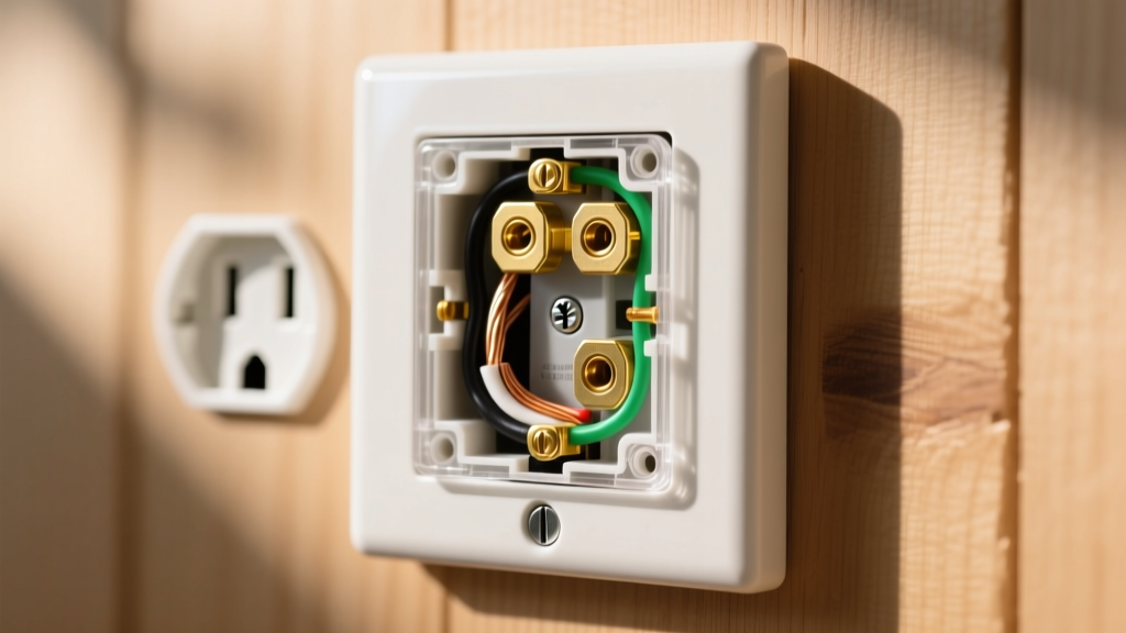
To diagnose internal failures, you must understand the mechanical components hidden behind the plastic faceplate. A standard NEMA 5-15R or 5-20R receptacle consists of several critical sub-assemblies:
1. The Yoke (Strap)
The metal mounting strap that secures the device to the electrical box. In premium spec-grade receptacles (like the Leviton 5262-SW, priced around $4.50 in 2026), the yoke is made of thick, zinc-plated steel that resists bending during installation, ensuring the internal wipers remain perfectly aligned. Builder-grade models ($1.10) use thinner brass or plated steel that can warp, causing internal contact misalignment.
2. Internal Wiper Contacts
These are the spring-loaded brass or phosphor-bronze fingers that grip the male blades of an attachment plug. Over time, thermal cycling causes metal fatigue. If a wiper loses its spring tension, it creates a high-resistance connection, leading to arcing and thermal runaway.
3. Break-Off Fins (Tabs)
Located on the hot (brass) and neutral (silver) terminal sides, these small metal tabs allow the top and bottom receptacles to be fed from the same circuit. Breaking the hot tab is standard practice for split-wired (switched) receptacles. A common diagnostic error occurs when a previous installer breaks the neutral tab by mistake, leaving the bottom half of the receptacle completely dead while the top half functions normally.
Diagnostic Matrix: Receptacle Failure Modes & Multimeter Readings
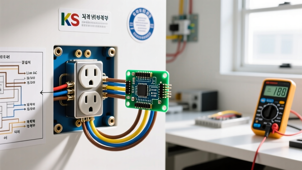
When troubleshooting, visual inspection is rarely enough. You must use a True RMS multimeter (such as the Fluke 117 or Klein Tools MM700) to measure voltage under load. Below is a diagnostic matrix for common internal and terminal failures.
| Symptom Reported | Multimeter Reading (No Load / Under Load) | Internal Failure Point | Pro Remediation & Cost |
|---|---|---|---|
| Vacuum cleaner randomly shuts off when wiggling the cord. | 120V (No Load) / Drops to 45V (Under 10A Load) | Internal wiper fatigue; loss of spring tension on the hot slot. | Replace with Spec Grade (e.g., Leviton 5262). Cost: ~$4.50 + 10 mins. |
| Downstream receptacles are dead; this one works. | 120V Line-to-Neutral / 0V on Load-side terminals. | Push-in (backstab) connector failure on the load-side neutral. | Remove backstabs, pigtail wires, and terminate on screw terminals. |
| Melted plastic discoloration near the shorter (hot) slot. | Voltage fluctuates between 115V and 118V; thermal camera shows 140°F+. | High-resistance joint due to loose terminal screw or aluminum wire oxidation. | Use CO/ALR rated device or Alumiconn pigtails. Torque to 14 in-lbs. |
| Plug-in tester shows "Open Ground" but wires look connected. | 120V Hot-to-Neutral / 0V Hot-to-Ground / 0V Neutral-to-Ground. | Bootleg ground (neutral-to-ground jumper) or broken ground wiper. | Verify ground path to panel; remove illegal neutral-ground bond. |
The Physics of "Backstab" Push-In Connection Failures
One of the most frequent causes of intermittent outlet failures in homes built between 1980 and 2010 is the use of push-in (backstab) terminals. While the NEC and OSHA Electrical Safety Guidelines permit their use on 14 AWG copper wire, they are a primary failure point in troubleshooting scenarios.
The Failure Mechanism: Backstab connections rely on a small internal steel or beryllium-copper spring to bite into the solid copper wire. Copper and steel have different coefficients of thermal expansion. When a high-draw device (like a 1500W space heater pulling 12.5A) is used, the wire heats up and expands. When unplugged, it cools and contracts. Over 5 to 10 years of this thermal cycling, the internal spring loses its mechanical tension. The connection becomes loose, increasing electrical resistance. According to Ohm's Law (P = I²R), increased resistance under a 12.5A load generates massive amounts of heat, eventually melting the polycarbonate faceplate and creating a severe arc-fault fire hazard.
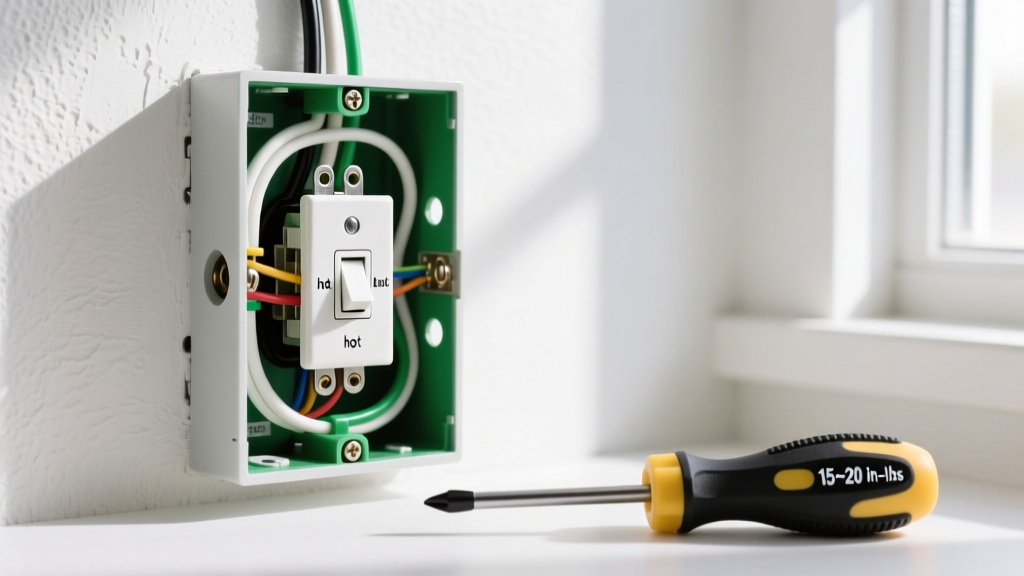
Diagnostic Step: If you are troubleshooting a dead downstream circuit, always pull the upstream receptacle out of the box. If you see 14 AWG wires stabbed into the back, immediately cut them out, strip them, and terminate them under the side screw terminals using a torque screwdriver set to the manufacturer's specification (typically 14 in-lbs for 14-10 AWG wire, as highlighted by Electrical Contractor Magazine regarding NEC 110.14(D) compliance).
Advanced Diagnostics: Identifying Bootleg Grounds
A "bootleg ground" is a deceptive and highly dangerous code violation where a previous DIYer or handyman installs a jumper wire between the neutral (silver) terminal and the ground (green) terminal on a 2-prong ungrounded circuit to trick a home inspector's plug-in tester.
How to Diagnose a Bootleg Ground
- Do not trust a $10 plug-in tester. It will falsely read "Correct Wiring" because it simply checks for continuity between neutral and ground.
- Measure Neutral-to-Ground Voltage: Set your True RMS multimeter to AC Voltage. Place the black probe on the Neutral slot and the red probe on the Ground slot. In a properly wired system, this should read less than 2.0V. If it reads exactly 0.0V, or if it reads line voltage (120V) when a load is applied elsewhere on the circuit, you likely have a bootleg ground.
- The Load Test: Plug a high-wattage hair dryer into the receptacle and turn it on. Measure Hot-to-Ground. If the voltage drops significantly or the ground slot becomes energized relative to a known true ground (like a copper water pipe), the ground is fake and is carrying return current. This poses a lethal shock hazard if the neutral wire ever disconnects upstream.
GFCI Receptacle Internal Diagnostics
When troubleshooting Ground Fault Circuit Interrupter (GFCI) outlets, the definition of electrical outlet expands to include solid-state sensing circuitry. Modern GFCIs (such as the 2026 Leviton SmartlockPro series) contain an internal sensing toroid that measures the current differential between the hot and neutral conductors. If the differential exceeds 4mA to 6mA, an internal Silicon Controlled Rectifier (SCR) trips the mechanical solenoid.
Edge Case Failure: If a GFCI refuses to reset, and you have verified 120V is present on the LINE terminals, the internal SCR has likely failed in the open position, or the self-test microchip has detected a degraded component and initiated a permanent lockout. Unlike older models that could fail "open" and still pass power without protection, modern UL-listed GFCIs are designed to fail completely dead to prevent false security. There is no internal repair for this; the entire receptacle must be replaced.
Summary: A Professional Approach to Outlet Troubleshooting
Mastering the true definition of electrical outlet and understanding the mechanical realities of receptacle anatomy separates amateur guesswork from professional diagnostics. By utilizing True RMS multimeters, understanding thermal expansion physics in push-in terminals, and rigorously testing for deceptive bootleg grounds, you can accurately pinpoint failure modes, ensure compliance with the latest NEC standards, and guarantee long-term electrical safety in any residential or commercial environment.