
The Critical Importance of 240V Receptacle Inspection
As modern kitchens increasingly adopt high-draw induction ranges and advanced convection electric stoves in 2026, the electrical infrastructure powering them faces unprecedented demand. An electric stove plug outlet is not a standard receptacle; it is a high-current 240V junction that, if degraded or improperly wired, poses a severe fire and shock hazard. According to the National Fire Protection Association (NFPA), cooking equipment remains the leading cause of home structure fires, with electrical failures and arcing at high-amperage receptacles accounting for a significant subset of these incidents.
This comprehensive inspection and testing guide provides domain-level expertise for evaluating NEMA 14-50 and 14-30 receptacles. Whether you are troubleshooting a stove that fails to heat, verifying a new installation, or inspecting an older home's kitchen wiring, this protocol ensures safety, code compliance, and optimal appliance performance.
⚠️ HIGH VOLTAGE WARNING: A 240V circuit carries enough current to cause fatal electrocution and severe arc flashes. Never probe a live receptacle without Category III (CAT III) or Category IV (CAT IV) rated testing equipment. If you lack experience with high-voltage diagnostics, hire a licensed electrician.
Identifying Your Electric Stove Plug Outlet Configuration
Before testing, you must identify the specific NEMA (National Electrical Manufacturers Association) configuration of your receptacle. The National Electrical Code (NEC) has evolved, and older homes may still feature obsolete 3-prong setups that lack a dedicated equipment grounding conductor.
| NEMA Type | Amperage | Wire Configuration | Wire Gauge (Copper) | Current Code Status (2026) |
|---|---|---|---|---|
| 14-50R | 50A | 4-Prong (Hot, Hot, Neutral, Ground) | 6 AWG | Standard for modern electric/induction ranges |
| 14-30R | 30A | 4-Prong (Hot, Hot, Neutral, Ground) | 10 AWG | Used for older or lower-wattage dryers/stoves |
| 10-50R | 50A | 3-Prong (Hot, Hot, Neutral/Ground bonded) | 6 AWG | Obsolete; grandfathered but not permitted in new installs |
Essential Diagnostic Tools for 240V Testing
Standard 120V receptacle testers (the simple plug-in devices with three neon lights) are useless for an electric stove plug outlet. You need specialized, high-voltage-rated equipment to accurately diagnose 240V circuits.
- True RMS Digital Multimeter (CAT III 600V minimum): The Fluke 117 or Klein Tools MM700 are industry standards. True RMS is vital for reading accurate voltages on circuits that may have harmonic distortion from modern inverter-based appliance power supplies.
- Non-Contact Voltage Tester (NCVT): A dual-range NCVT (like the Fluke 2AC-II) helps verify the presence of voltage before making direct contact.
- Thermal Imaging Camera: Devices like the FLIR ONE Gen 3 or Seek Thermal CompactPRO are invaluable for detecting invisible resistive heating at terminal connections.
- Calibrated Torque Screwdriver: NEC Article 110.14(D) mandates that terminations be torqued to the manufacturer's specifications. A Klein Tools 60055 torque driver ensures lugs are tightened to the exact inch-pound rating (typically 35-50 in-lbs for 50A receptacles).
Step-by-Step Inspection & Testing Protocol
Phase 1: Visual and Thermal Inspection (De-Energized)
- Shut Off Power: Turn off the 240V double-pole breaker at the main service panel. Verify it is locked out or tagged out so no one accidentally restores power.
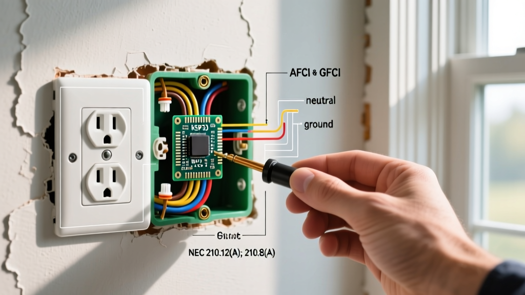
- Extract the Receptacle: Remove the faceplate and unscrew the receptacle from the junction box. Gently pull the electric stove plug outlet forward to expose the terminal lugs and wiring.
- Inspect for Thermal Damage: Look for brown or black scorch marks on the brass hot terminals or the plastic housing. This indicates 'aluminum creep' or loose copper connections causing resistive heating. If the plastic is warped or brittle, the receptacle (e.g., a Leviton 279-S00 or Hubbell 9450A) must be replaced immediately.
- Check Wire Gauge and Type: Verify the wire matches the breaker. A 50A breaker requires 6 AWG copper or 4 AWG aluminum. If you find 8 AWG copper on a 50A breaker, the circuit is dangerously undersized and violates NEC Article 240.4.
Phase 2: Live Voltage Testing
Restore power at the breaker. Set your multimeter to AC Voltage (V~). Keep one hand behind your back to prevent current from crossing your chest in the event of a shock.
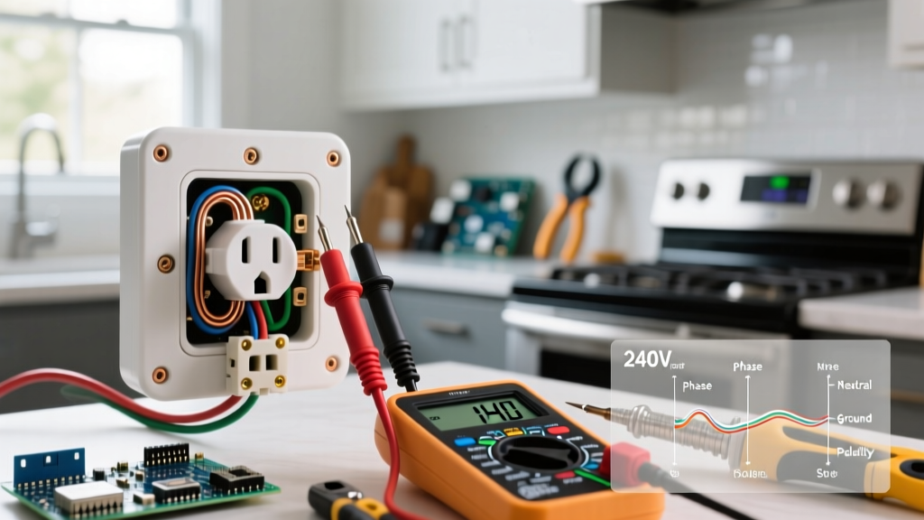
- Hot-to-Hot (L1 to L2): Insert probes into the two vertical angled slots. Expected reading: 240V (±5%).
- Hot-to-Neutral (L1 to Neutral / L2 to Neutral): Measure from each hot slot to the horizontal neutral slot. Expected reading: 120V for each.
- Hot-to-Ground (L1 to Ground / L2 to Ground): Measure from each hot slot to the U-shaped ground pin. Expected reading: 120V.
- Neutral-to-Ground: Measure between the neutral slot and the ground pin. Expected reading: 0V to 2V. A reading higher than 3V indicates a loose neutral connection at the main panel or a bonded neutral/ground downstream, which is a severe code violation.
Advanced Diagnostics: Aluminum Wire and Torque Failures
Homes built between the late 1960s and early 1980s frequently utilized aluminum branch circuit wiring for 240V appliances. Aluminum expands and contracts at a different rate than copper or brass terminals. Over years of heating cycles (every time you bake or broil), the aluminum wire 'creeps' out from under the terminal lug, creating a high-resistance gap.
This gap causes micro-arcing, generating extreme heat that melts the receptacle face and can ignite surrounding wood framing. The U.S. Consumer Product Safety Commission (CPSC) has long warned about the hazards of unmitigated aluminum wiring. If your inspection reveals aluminum wire, the receptacle must be rated CO/ALR, and the terminations must be treated with an antioxidant compound like Noalox to prevent oxidation. Furthermore, you must use a calibrated torque screwdriver to tighten the lugs to the exact specification printed on the receptacle yoke; over-torquing can snap the softer aluminum wire, while under-torquing guarantees future arcing.
Common Failure Modes & Troubleshooting Matrix
When an electric range malfunctions, the issue is often traced back to the electric stove plug outlet rather than the appliance itself. Use this matrix to diagnose specific symptoms.
| Appliance Symptom | Likely Electrical Cause | Diagnostic Verification & Fix |
|---|---|---|
| Clock and oven light work, but burners and oven do not heat. | Lost 240V supply. One of the two hot legs (L1 or L2) is dead. The 120V accessories run on the remaining leg. | Test L1-L2 at the receptacle. If 120V instead of 240V, check the double-pole breaker for a tripped half, or look for a burned-off wire at the panel lug. |
| Stove clicks continuously; digital display flickers or resets. | Lost or high-resistance Neutral connection. The 120V control board is starving for current. | Test Neutral-to-Ground. If voltage fluctuates or reads high, tighten the neutral lug at both the receptacle and the main panel. |
| Breaker trips immediately when the oven is turned on. | Dead short in the appliance wiring, or a melted receptacle causing L1/L2 to arc across the internal brass contacts. | Inspect the receptacle internals for carbon tracking (black soot bridging the terminals). Replace the receptacle and megger-test the stove cord. |
| Receptacle face feels hot to the touch during normal baking. | Loose terminal connections causing resistive heating, or undersized wire (e.g., 8 AWG on a 50A breaker). | Use a thermal camera to locate the exact hot spot. De-energize, re-strip wires, apply antioxidant (if aluminum), and torque to spec. |
3-Prong to 4-Prong Upgrade Considerations
If you are inspecting an older home, you will likely encounter a NEMA 10-50 (3-prong) electric stove plug outlet. The NEC banned new installations of 3-prong range receptacles decades ago because they rely on the neutral wire to act as the equipment ground. If the neutral wire breaks, the metal chassis of the stove becomes energized at 120V, posing a lethal shock hazard.
While existing 3-prong setups are 'grandfathered' by the Electrical Safety Foundation International (ESFI) and local codes, upgrading to a 4-wire NEMA 14-50 circuit is highly recommended for safety. This requires pulling a new 4-conductor cable (6/3 with ground) from the panel. Crucially, when connecting a 4-prong cord to the stove, the installer must remove the green bonding jumper strap on the stove's terminal block that ties the neutral to the chassis. Failing to remove this strap on a 4-wire system creates a parallel neutral path, causing current to flow on the ground wire and creating a shock hazard.
Final Verification and Reassembly
Once testing is complete and any necessary repairs or torque adjustments have been made, carefully fold the heavy-gauge wires back into the junction box. Ensure no bare copper ground wires are touching the brass hot terminals. Secure the receptacle to the box using the provided machine screws, ensuring it sits perfectly plumb. Attach the cover plate, restore power, and perform one final live voltage check at the receptacle face before plugging in the range. By adhering to this rigorous inspection protocol, you ensure the safe, efficient, and code-compliant operation of the kitchen's most power-hungry appliance.