
Wiring a standard 15-amp or 20-amp duplex receptacle is one of the most common electrical tasks in residential maintenance, yet it remains a primary source of preventable house fires. According to the Electrical Safety Foundation International (ESFI), electrical malfunctions cause tens of thousands of home fires annually, with loose or improper receptacle connections acting as a major catalyst for arc faults and thermal degradation. Understanding exactly how to connect electrical wires to outlet configurations is not just about making the power work; it is about ensuring long-term mechanical stability and strict adherence to the National Electrical Code (NEC).
This comprehensive safety and code compliance guide will walk you through the precise mechanics of receptacle wiring, from wire stripping tolerances to the mandatory torque specifications introduced in recent NEC cycles. Whether you are upgrading to Tamper-Resistant (TR) models or replacing a burnt-out 20A commercial unit, these protocols will ensure your installation is safe, durable, and inspector-approved.
Essential NEC-Compliant Tools & Materials
Before addressing how to connect electrical wires to outlet terminals, you must assemble the correct tools. The days of using a pocket knife to strip wire or guessing screw tightness are over. Modern code compliance requires precision.
- Wire Strippers: Use a dedicated gauge-matched stripper like the Klein Tools 11063W (for 14-10 AWG). This ensures you do not nick the copper conductor, which creates a weak point prone to snapping under the screw head.
- Torque Screwdriver: NEC 110.14(D) mandates that terminals be tightened to the manufacturer's specified torque. A calibrated torque screwdriver, such as the CDI 401SM (10-50 in-lb range), is now a mandatory tool for professional compliance.
- Non-Contact Voltage Tester: A dual-range tester like the Fluke 1AC-II or Klein NCVT-3 is required to verify a de-energized state before touching any bare copper.
- Receptacles: Per NEC 406.12, all 15A and 20A, 125V and 250V receptacles installed in dwelling units must be listed as Tamper-Resistant (TR). Look for models like the Leviton T5320-W (15A TR) or Hubbell 5362 (20A commercial grade).
The Precision of Wire Stripping: The Strip Gauge Rule
The most frequent failure mode in DIY outlet wiring stems from improper wire stripping. If you strip too much insulation, you leave bare copper exposed outside the terminal yoke, creating a severe shock and short-circuit hazard. If you strip too little, the insulation gets trapped under the brass terminal screw, resulting in a high-resistance connection that will generate excessive heat and eventually melt the receptacle face.
Using the Manufacturer's Strip Gauge
Every UL-listed receptacle features a physical 'strip gauge' molded into the back of the thermoplastic yoke. For standard 14 AWG and 12 AWG solid copper wire, this gauge typically dictates a strip length between 5/8-inch and 3/4-inch. Always lay your stripped wire against this physical gauge before forming your connection. When learning how to connect electrical wires to outlet screws, this 3/4-inch rule is your first line of defense against thermal failure.
Connection Methods: Screw Terminals vs. Push-In Back-Wiring
When examining the back of a modern receptacle, you will typically see three connection options. Understanding the code and safety implications of each is critical.
| Connection Type | Mechanism | Code & Safety Verdict | Best Use Case |
|---|---|---|---|
| Side Wiring (Screw Terminals) | Wire wrapped around brass/green screw. | Gold Standard. Maximum surface area contact. Highly reliable when torqued to spec. | All residential and commercial applications. |
| Back Wiring (Screw-Clamp) | Wire inserted into hole, clamped by tightening a separate screw. | Excellent. Often found on commercial/spec-grade receptacles. Provides immense holding pressure. | High-vibration areas, 20A heavy-load circuits. |
| Push-In (Back-Stab) | Wire pushed into spring-loaded hole. | Poor / Discouraged. Spring tension degrades over time due to thermal expansion/contraction cycles. | Strictly limited to 15A circuits with 14 AWG solid wire only. |
Expert Warning: While UL still lists push-in (back-stab) connectors for 14 AWG wire on 15A receptacles, the Consumer Product Safety Commission (CPSC) and veteran electricians universally advise against them. The internal brass spring clips loosen under the thermal expansion and contraction of high-draw appliances (like space heaters or vacuum cleaners), leading to arcing and melted receptacles. Always use side-wiring or screw-clamp back-wiring for permanent safety.
Step-by-Step: How to Connect Electrical Wires to Outlet Safely
Follow this exact sequence to ensure a mechanically sound and code-compliant connection.
- De-energize and Verify: Turn off the circuit breaker. Test the existing outlet with your NCVT-3 and a plug-in receptacle tester to confirm zero voltage. Never assume a wire is dead based on the breaker label alone.
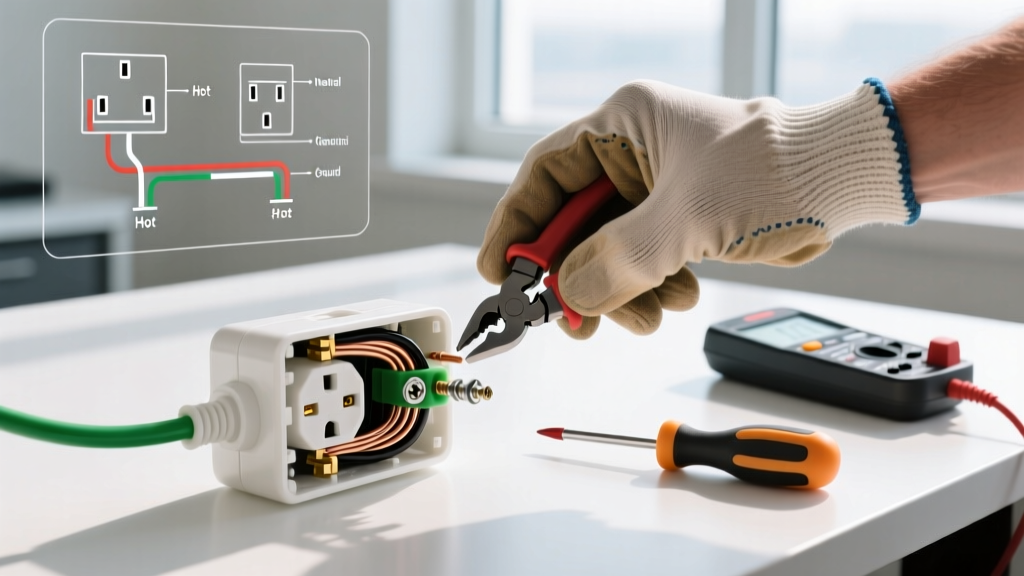
- Form the Clockwise J-Hook: Using needle-nose pliers, bend the stripped end of the solid copper wire into a tight 'J' or fish-hook shape. Critical Rule: The hook must curve clockwise. When you tighten the terminal screw (which turns clockwise), the screw head will pull the loop tighter around the shaft. A counter-clockwise loop will be pushed out from under the screw as it tightens.
- Seat the Wire Properly: Slide the hook under the screw head so the wire sits flat against the brass contact plate. Ensure no insulation is trapped under the screw, and no bare copper is visible extending past the yoke.
- Torque to Specification: This is where NEC 110.14(D) comes into play. Check the back of the receptacle or the manufacturer's spec sheet for the torque requirement. For most standard 15A and 20A Leviton and Hubbell receptacles, the required torque is 14 in-lbs. Set your torque screwdriver and tighten until it clicks. This prevents both under-tightening (which causes arcing) and over-tightening (which strips the brass threads or snaps the screw).
- Connect the Ground: The bare copper or green insulated ground wire connects to the green grounding screw. If you are daisy-chaining outlets, you must use a grounding pigtail or a listed grounding clip to maintain the ground path continuity, per NEC 250.148.
Advanced Code Compliance: Box Fill Calculations
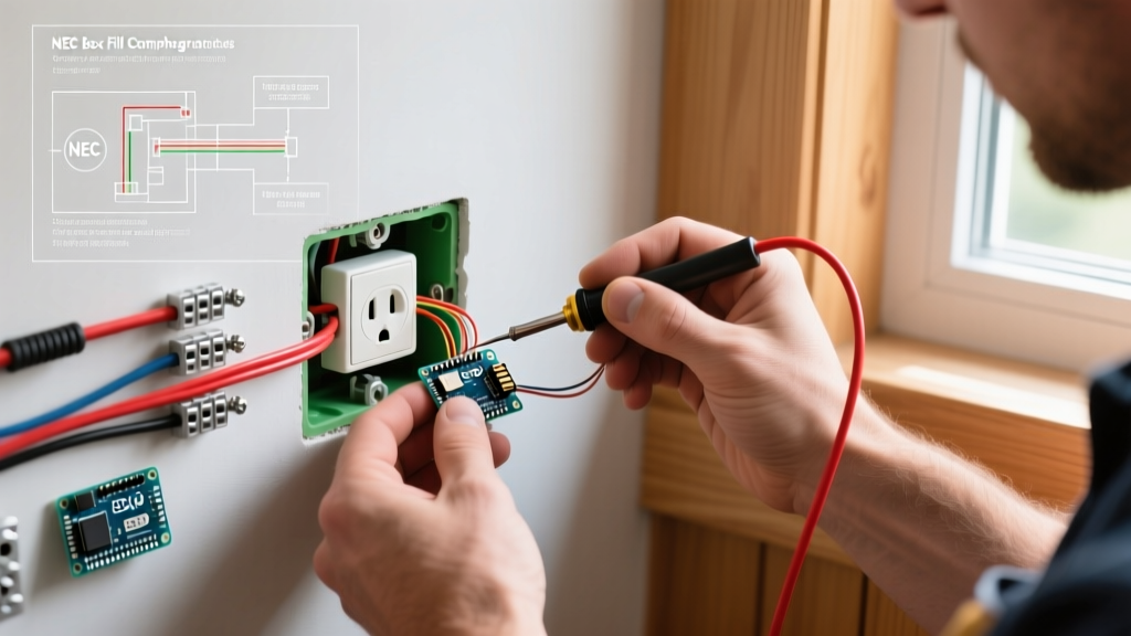
Knowing how to connect electrical wires to outlet terminals is only half the battle; the environment housing those connections must also meet NEC standards. NEC Article 314.16 dictates 'Box Fill' calculations to prevent overcrowding, which can crush wire insulation and trap heat.
To calculate if your electrical box is legally sized, assign a cubic inch (cu in) value to every conductor and device inside the box:
- 14 AWG Wire: 2.0 cu in per conductor
- 12 AWG Wire: 2.25 cu in per conductor
- Receptacle Device: Counts as 2 wires (based on the largest wire connected to it)
- Ground Wires: All grounds combined count as 1 wire
- Internal Clamps: Count as 1 wire
Example: A standard single-gang plastic nail-on box is typically 18 cu in or 22.5 cu in. If you are pushing three 12/2 Romex cables into a box with a 20A receptacle, your fill calculation will easily exceed 18 cu in, requiring a deeper 'outlet box' to remain code-compliant and safe.
GFCI Receptacles: The Line vs. Load Distinction
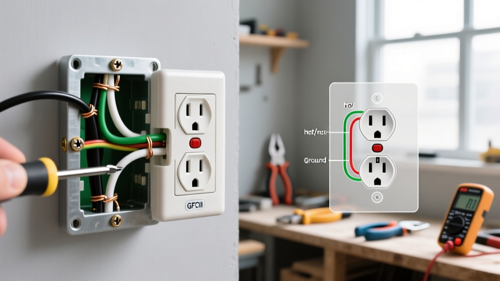
When wiring Ground Fault Circuit Interrupter (GFCI) outlets in kitchens, bathrooms, or garages (mandated by NEC 210.8), the connection process becomes more complex. GFCI receptacles feature two distinct sets of terminals: LINE and LOAD.
- LINE: This is where the incoming power from the breaker panel connects. If you connect power to the LOAD terminals by mistake, the outlet will appear to work, but it will provide zero ground-fault protection, creating a lethal safety hazard.
- LOAD: These terminals are only used if you intend to protect downstream 'daisy-chained' standard receptacles. If you are only protecting the single GFCI outlet, leave the LOAD terminals empty and cap the downstream wires.
Frequently Asked Questions (Code & Safety)
Can I use 14 AWG wire on a 20-amp outlet?
No. NEC 210.21 strictly prohibits 14 AWG wire on 20-amp circuits. Furthermore, a 20-amp receptacle (identified by the T-shaped neutral slot) cannot be installed on a 15-amp circuit. You must match the wire gauge, breaker size, and receptacle rating perfectly.
Is it code-compliant to 'back-stab' wires into the outlet?
While technically permitted by UL for 14 AWG wire on 15A circuits, it is heavily discouraged by safety experts and local inspectors due to the high failure rate of the internal spring clips. Side-wiring with a torque screwdriver is the only recommended method for long-term reliability.
What is a 'bootleg ground' and why is it dangerous?
A bootleg ground occurs when a jumper wire is installed between the neutral (silver) terminal and the ground (green) screw to trick a receptacle tester into reading 'Correct'. This is a severe NEC violation. If the neutral wire ever becomes disconnected upstream, the metal chassis of any plugged-in appliance will become energized with 120V, posing an immediate electrocution risk. For ungrounded older homes, NEC 406.4(D) allows specific remedies, such as installing a GFCI receptacle marked 'No Equipment Ground'.
Final Thoughts on Receptacle Safety
Mastering how to connect electrical wires to outlet configurations requires moving beyond simple 'plug-and-play' mentalities. By respecting the physics of thermal expansion, utilizing torque-calibrated tools, and strictly adhering to NFPA 70 (National Electrical Code) standards, you ensure that your electrical system remains safe, efficient, and fully compliant for decades to come. Always consult a licensed master electrician if your home's wiring lacks a ground path or shows signs of aluminum conductor degradation.