
The 2-Wire Combo Device Dilemma: What You Are Actually Looking At
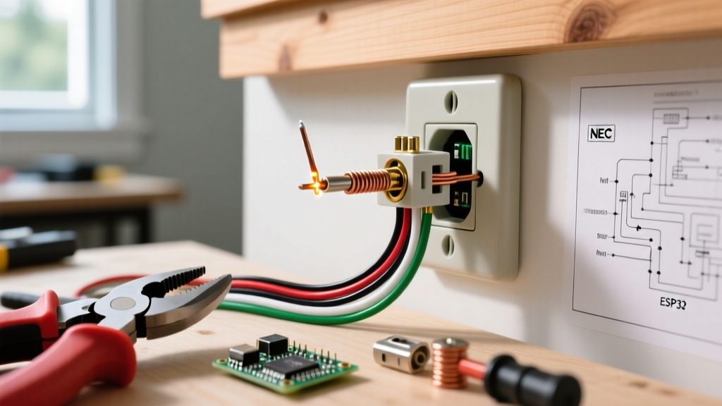
Opening a 1-gang junction box in a pre-1970s home to find a single cable with only two current-carrying wires is one of the most common—and misunderstood—scenarios in residential electrical upgrades. When homeowners search for a wiring diagram for light switch and outlet with 2 wires, they are usually attempting to replace an aging, ungrounded combo switch/receptacle (a single yoke housing both a toggle switch and a 15A outlet).
However, generic wiring diagrams fail to account for the critical topological differences of a 2-wire feed. Before you purchase a replacement device like the Leviton 5224-W or a modern GFCI combo, you must diagnose the exact function of those two wires. Misidentifying a switch loop as a neutral feed will result in a catastrophic dead short or a severe shock hazard.
Diagnostic Phase: Identifying Your 2-Wire Topology
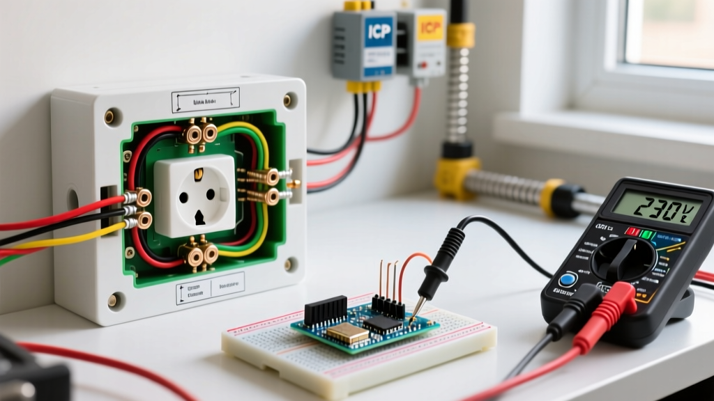
There are only three possible realities when you see 'two wires' in a switch/outlet box. Use a non-contact voltage tester (like the Klein Tools NCVT-2, ~$22) and a multimeter to determine which topology you have.
Topology 1: The Classic Switch Loop (No Outlet Possible)
In older wiring methods, power was routed to the ceiling light fixture first, and a single 2-wire cable was dropped down to the wall switch.
- Wire 1 (White): Re-identified as Line Hot (should have black tape/paint). Constant 120V.
- Wire 2 (Black): Switched Hot returning to the light fixture.
- The Verdict: There is no neutral wire in this box. You cannot wire an outlet here. Any attempt to wire a receptacle will either fail to power the device or create a direct short across the lighting circuit. You must pull a new 12/2 or 14/2 NM-B cable from a nearby receptacle box to add an outlet.
Topology 2: The End-of-Run Combo Feed (Switch Controls Outlet)
Power originates at the panel and terminates at this specific 1-gang box. The cable contains a Line Hot and a Line Neutral, but no downstream loads.
- Wire 1 (Black): Line Hot (120V constant).
- Wire 2 (White): Line Neutral (0V to ground).
- The Verdict: You can wire a combo device, but the integrated switch only controls the bottom half of the receptacle on the same yoke. You cannot wire a separate ceiling light from this box unless you are using a smart-bulb socket adapter or the 'light' is a lamp plugged into the switched outlet.
Topology 3: The 'Hidden' Ground (Standard 2-Wire NM-B)
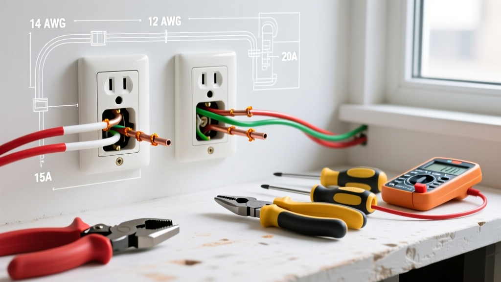
Many DIYers refer to 14/2 or 12/2 Romex as '2 wires' because it has two current-carrying conductors (Black and White), forgetting the bare copper equipment grounding conductor (EGC).
- Wire 1 (Black): Line Hot.
- Wire 2 (White): Line Neutral.
- Wire 3 (Bare Copper): Equipment Ground.
- The Verdict: Full combo wiring is possible, and standard 3-prong replacements are perfectly legal and safe.
NEC 2026 Code Requirements for Ungrounded 2-Wire Upgrades
If your home has true 2-wire ungrounded circuitry (common in cloth-sheathed wiring or early metallic conduit systems without a ground path), you are bound by NEC Article 406.4(D).
Code Alert: You cannot legally install a standard 3-prong combo device (like the Leviton 5224-W) on an ungrounded 2-wire circuit. Under NEC 406.4(D)(3), replacements on ungrounded circuits must be protected by a Ground Fault Circuit Interrupter (GFCI). Furthermore, the faceplate must be labeled 'No Equipment Ground' and 'GFCI Protected'.
According to the Consumer Product Safety Commission (CPSC), GFCI protection prevents over two-thirds of the roughly 300 annual home electrocutions. Upgrading to a GFCI combo device is not just a code requirement; it is a critical life-safety intervention.
Text-Based Wiring Diagram: GFCI Combo on a 2-Wire Ungrounded Feed
For Topology 2 (End-of-Run Feed with Hot and Neutral, but NO ground), the optimal 2026 upgrade path is the Pass & Seymour 2095-GCCD3 (20A GFCI Combo Switch/Receptacle, approx. $42). This device provides shock protection without requiring an equipment ground.
Connection Map
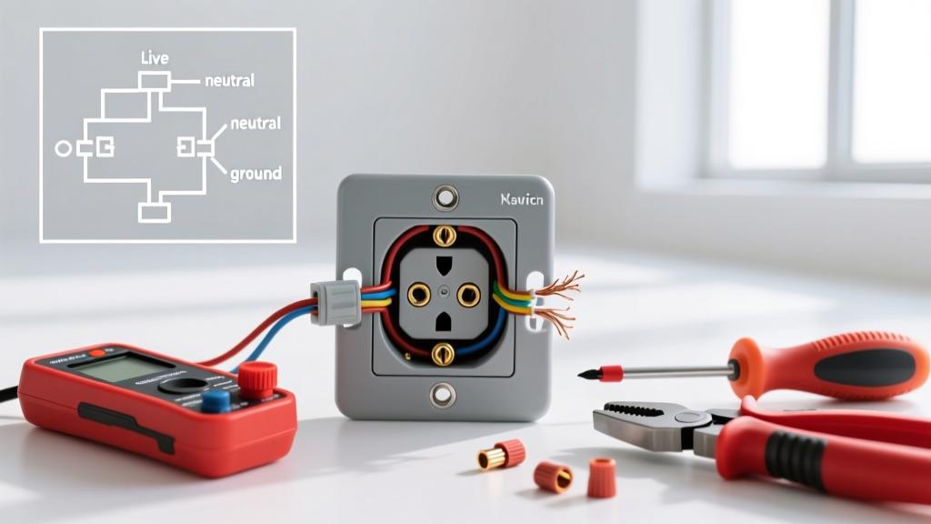
| Cable Wire | Device Terminal | Screw Color / Label | Function |
|---|---|---|---|
| Black (Line Hot) | LINE Hot | Brass (Black Label) | Provides 120V power to the GFCI sensing circuit. |
| White (Line Neutral) | LINE Neutral | Silver (White Label) | Completes the circuit for the GFCI electronics. |
| Bare/Armor (If present) | Ground Screw | Green | DO NOT connect to neutral. Leave capped if ungrounded. |
| Internal Jumper | Switch Output | Brass (Load Side) | Routes GFCI-protected power to the bottom receptacle. |
Note: The 'LOAD' terminals on the GFCI combo are left empty in an end-of-run scenario, as there are no downstream devices to protect.
Step-by-Step Upgrade Procedure
- Kill the Power & Verify: Turn off the breaker. Use a Fluke T5-600 (~$185) to test between the black wire and the metal box (if metal) or a known ground. Confirm 0V.
- Remove the Old Device: Unscrew the yoke. Take a photo of the existing brass fin (break-off tab) on the hot side. On a combo device, the hot-side tab must be broken to isolate the switch from the always-hot top receptacle (if configured for half-switched). On the P&S 2095-GCCD3, internal logic handles this, but always read the included schematic.
- Prepare the Wires: Strip 3/4 inch of insulation using Ideal 33-080 wire strippers. Do not nick the copper, which creates a high-resistance hot spot.
- Make the Connections: Loop the black wire clockwise around the LINE Hot brass screw. Torque to 14 in-lbs. Repeat for the white wire on the LINE Neutral silver screw.
- Address the Missing Ground: If the box is metal but ungrounded, pigtail a copper wire to the box's grounding clip and connect it to the device's green screw only if you have verified continuity to the panel ground. If unverified, leave the green screw empty and apply the 'No Equipment Ground' sticker to the nylon faceplate.
- Test the GFCI: Restore power. Press the 'TEST' button on the device. The outlet should trip, and the switch should lose power to the bottom receptacle. Press 'RESET'.
Common Failure Modes & Edge Cases
When working with legacy 2-wire systems, electricians frequently encounter these hazardous edge cases:
- The 'Bootleg' Ground: Previous owners may have installed a jumper wire between the neutral silver screw and the green ground screw to trick a 3-prong tester. This is lethal. If a neutral fault occurs upstream, the metal casing of whatever you plug in becomes energized at 120V. Always remove bootleg jumpers during upgrades.
- Reversed Polarity on Switch Loops: If you mistakenly wire the white wire of a switch loop to the neutral terminal of a combo outlet, you are tying the switched hot directly to the panel's neutral bus via the load. This will instantly trip the breaker or melt the 14 AWG wire if the breaker fails.
- Shared Neutral Multi-Wire Branch Circuits (MWBC): Rare in 1-gang switch boxes, but if you find two hots and one shared neutral, a standard GFCI combo will not work without separating the neutrals, which is impossible in a 2-wire constraint.
Upgrade Options Comparison Matrix
| Upgrade Path | Estimated Cost | NEC 2026 Compliant? | Safety Level | Best Use Case |
|---|---|---|---|---|
| Standard Combo (Leviton 5224-W) | $8 | No (if ungrounded) | Low (No shock protection) | Only for verified grounded 12/2 or 14/2 circuits. |
| GFCI Combo (P&S 2095-GCCD3) | $42 | Yes (with labels) | High (5mA trip threshold) | Ungrounded 2-wire end-of-run feeds. |
| Rewire with 12/2 NM-B + Ground | $150 - $300+ | Yes (Full compliance) | Maximum | When adding a true separate ceiling light and grounded outlet. |
Final Safety Directives
Upgrading a wiring diagram for light switch and outlet with 2 wires requires strict adherence to diagnostic protocols. Never assume a white wire is a neutral, and never assume a metal junction box is grounded. For comprehensive residential safety standards and grounding requirements, always consult the NFPA Home Electrical Safety guidelines. If your diagnostic testing reveals a switch loop where an outlet is desired, stop work and consult a licensed electrician to pull a new neutral feed; there is no safe code-compliant workaround for a missing neutral conductor.