
Decoding the Chevy 350 Electrical Ecosystem
The Small Block Chevrolet (SBC) 350 remains one of the most prolific V8 engines in automotive history. While mechanical rebuilds are heavily documented, the electrical harness—specifically the critical connectors and ignition routing—is often misunderstood. When searching for a comprehensive plug wiring diagram for Chevy 350 applications, enthusiasts frequently conflate spark plug wire routing with electrical connector pinouts. Both are vital for engine operation, but they require entirely different diagnostic approaches, wire gauges, and termination techniques.
This reference guide bridges that gap. We will dissect the three most critical 'plug' systems on a Chevy 350: the GM High Energy Ignition (HEI) distributor connector, the Delco Remy alternator pigtail, and the high-voltage spark plug wire routing diagram. Whether you are performing an EFI swap, restoring a 1970s GM A-body, or troubleshooting a no-start condition in 2026, understanding these specific node connections is mandatory.
HEI Distributor Plug: Pinouts and the Ballast Bypass
Introduced in 1974, the GM HEI system integrated the ignition coil and module directly into the distributor cap. The main harness plug that mates to the HEI cap is a common failure point, primarily due to improper voltage supply from legacy wiring harnesses.
The 4-Pin Ignition Module Connector
The external plug on the HEI cap interfaces with the internal 4-pin ignition module. Understanding the pinout is critical when fabricating a custom test harness or repairing a melted factory connector.
- BAT (Battery): Requires a full 12V to 14V supply during both 'Run' and 'Start' positions. This pin powers the primary side of the internal coil and the module logic.
- TACH (Tachometer): Outputs a 12V square wave pulse. This connects directly to the negative side of the coil internally and provides the signal for your dashboard tachometer or EFI system's RPM input.
- GND (Ground): Grounds the module to the distributor housing. Ensure the mating surfaces inside the distributor are free of dielectric grease and corrosion.
- NC (No Connection): The fourth pin on the standard 4-pin module is typically unused in basic street applications, though 5-pin modules use this for ESC (Electronic Spark Control) computer retard signals.
Expert Warning: Pre-1974 Chevy 350s equipped with points-style ignitions utilized a 'ballast resistor wire' (typically a pink or white cloth-braided 18 AWG wire) designed to drop voltage to 9V after the engine started to prevent point burnout. You must bypass this wire when upgrading to HEI. Feeding an HEI module 9V will result in weak spark, misfires under load, and premature module failure. Run a dedicated 12 AWG wire from an ignition-switched 12V fuse to the BAT terminal.
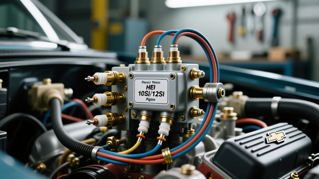
Delco Remy Alternator Pigtail Wiring (10SI / 12SI)
The Chevy 350 from the late 1960s through the 1980s predominantly used the Delco Remy 10SI and 12SI internally regulated alternators. The 2-pin plastic plug (pigtail) on the side of the alternator is the brain of the charging system. Miswiring this plug is the number one cause of 'overcharging' or 'dead battery' complaints in DIY restorations.
| Terminal Pin | Designation | Function & Wiring Destination | Recommended Wire Gauge |
|---|---|---|---|
| #1 (L) | Lamp / Exciter | Excites the alternator field to begin charging. Must route through the dash 'ALT/GEN' warning bulb (which provides necessary resistance) or a 50-ohm resistor to ignition-switched 12V. | 18 AWG (SAE J1128) |
| #2 (F) | Field / Sense | Senses actual system voltage to regulate output. Must connect directly to the battery positive terminal or the main starter junction block. Never jumper Pin 1 and Pin 2 together at the plug. | 12 AWG to 10 AWG |
According to SAE J1128 standards for low-tension primary automotive cable, wire insulation in engine bays must withstand continuous temperatures of 125°C. When replacing the brittle factory 10SI plug in 2026, always use modern Pico or Standard Motor Products molded pigtails featuring cross-linked polyethylene (XLPE) insulation rather than cheap PVC alternatives that will melt near exhaust manifolds.
Spark Plug Wire Routing Diagram & Firing Order
While not an 'electrical connector' in the traditional sense, the spark plug wire routing diagram is the most visually prominent wiring task on a Chevy 350. Incorrect routing leads to cross-fire induction, where the electromagnetic field of one firing wire induces a voltage spike in an adjacent wire, causing severe engine knock or backfires.
The SBC Firing Order Sequence
The universal firing order for the Chevrolet Small Block 350 is 1-8-4-3-6-5-7-2.
- Driver Side (Left Bank): Cylinders 1, 3, 5, 7 (Front to back)
- Passenger Side (Right Bank): Cylinders 2, 4, 6, 8 (Front to back)
- Distributor Rotation: Clockwise
Preventing Cross-Fire Induction (The 5-7 Conflict)
The most critical aspect of the Chevy 350 plug wiring diagram is managing cylinders 5 and 7. In the firing order, 5 fires immediately before 7. On the distributor cap, the terminals for 5 and 7 are physically adjacent to one another. Furthermore, on the driver-side cylinder head, the spark plugs for 5 and 7 are right next to each other.
Routing Solution: Never run the wires for cylinders 5 and 7 parallel to each other. Route them so they cross at a sharp 90-degree angle if they must intersect. Use separated wire looms and ensure the wire for cylinder 7 is routed toward the back of the engine bay, away from the cylinder 5 wire, to prevent electromagnetic induction from jumping the gap and firing cylinder 7 prematurely.
2026 Best Practices for Automotive Connector Terminals
Sourcing New Old Stock (NOS) GM pigtails in 2026 is nearly impossible, and the aftermarket is flooded with poorly stamped connectors. When repairing a Chevy 350 plug wiring diagram, the termination method is just as important as the routing.
- Open Barrel vs. Closed Barrel Crimps: Factory GM harnesses utilized open-barrel (F-style) crimps. If you are using standard closed-barrel butt splices, you must use a ratcheting hex-crimp tool. Pliers do not provide the necessary gas-tight deformation to prevent oxygen ingress and subsequent green copper corrosion.
- Adhesive-Lined Heat Shrink: Standard electrical tape will unwrap in an engine bay due to heat cycling and oil exposure. Every splice made near the HEI plug or alternator pigtail must be sealed with dual-wall, adhesive-lined polyolefin heat shrink tubing. The inner meltable adhesive layer creates a waterproof environmental seal, a requirement highlighted in modern AWG wire gauge and environmental protection guidelines.
- Dielectric Grease Application: Apply a small amount of dielectric grease to the female terminals of the HEI cap plug and the alternator pigtail before mating. This prevents fretting corrosion caused by engine vibration without impeding electrical conductivity at the contact patch.
Troubleshooting Common Chevy 350 Plug Failures
Even with a perfect plug wiring diagram for Chevy 350 setups, environmental factors cause specific failure modes. Use a digital multimeter (DMM) to diagnose these common issues:
Voltage Drop at the HEI BAT Terminal
With the engine running and the alternator charging (approx. 14.2V at the battery), place your DMM's red probe on the alternator output stud and the black probe on the HEI BAT terminal. A reading above 0.5V indicates excessive resistance in the ignition feed wire, usually caused by a corroded firewall bulkhead connector or a failing ignition switch. This voltage drop will cause the HEI module to starve and fail under heavy throttle.
Alternator Whine and the Exciter Wire
If your stereo emits a high-pitched whine that rises with engine RPM, check the alternator Pin 1 (Exciter) wire. If this wire is routed too close to the spark plug wires or the HEI TACH output, it will pick up high-frequency RFI (Radio Frequency Interference). Reroute the alternator pigtail along the firewall, away from the distributor and exhaust headers, to eliminate the noise.
Summary
Mastering the plug wiring diagram for Chevy 350 engines requires looking beyond simple color-coding. By ensuring full 12V delivery to the HEI module, correctly separating the Sense and Exciter circuits on the Delco alternator, and physically routing spark plug wires to defeat cross-fire induction, you guarantee reliable ignition and charging system performance. Always adhere to SAE wire standards and utilize modern environmental sealing techniques to ensure your SBC 350's electrical system survives the harsh under-hood environment for decades to come. For further reading on high-performance ignition upgrades, refer to the technical resources available via Holley's ignition system documentation.