
The Critical Importance of Post-Installation Outlet Verification
Installing a new receptacle is only half the job; verifying its safety and code compliance is where true electrical expertise lies. According to the U.S. Consumer Product Safety Commission (CPSC), faulty receptacles and degraded wiring connections are responsible for thousands of residential electrical fires annually. Knowing exactly how to check electrical outlet wiring ensures that polarity is correct, grounding paths are low-impedance, and termination torque meets modern National Electrical Code (NEC) standards.
This step-by-step guide moves beyond basic plug-in testers. We will cover professional-grade multimeter diagnostics, ghost voltage elimination, and the physical torque verification required by NEC 110.14(D). Whether you are commissioning a new 15A Leviton Decora or auditing an existing 20A commercial duplex, this protocol is your definitive checklist.
Essential Diagnostic Tool Stack (2026 Edition)
Before approaching the wall plate, assemble a professional testing toolkit. Relying on a $10 analog meter will not provide the safety margins or low-impedance filtering required for modern diagnostics.
- True-RMS Digital Multimeter with LoZ: The Fluke 117 (approx. $225) is the industry standard. Its AutoV/LoZ (Low Impedance) mode is mandatory for identifying phantom voltages caused by capacitive coupling in parallel cable runs.
- Dual-Range Non-Contact Voltage Tester (NCVT): The Klein Tools NCVT-3 (approx. $38) detects both standard (70–1000V) and low-voltage (12–48V) ranges, ensuring you do not miss induced voltages on shielded cables.
- Solenoid Voltage Tester: A classic Wiggy or modern electronic equivalent like the Fluke 2TL2 (approx. $65). Solenoid testers draw actual current, making them the only reliable way to catch "bootleg" grounds.
- Calibrated Torque Screwdriver: The Wiha 645T20 (approx. $110) with an adjustable torque setting to comply with NEC 110.14(D).
Step 1: Visual Inspection and Termination Audit
Before applying power, remove the receptacle from the electrical box and inspect the physical terminations. The most common installation failure is the use of "backstab" push-in terminals.
Side-Wiring vs. Backstabbing
Backstab terminals rely on a small internal spring clip that grips the wire. Over time, thermal cycling causes these springs to relax, leading to high-resistance connections and arc faults. Always use side-wiring terminals or the rear screw-and-clamp plates found on commercial-grade receptacles (like the Leviton 5362 or Hubbell 5262).
Expert Tip: If you encounter 14 AWG wire inserted into a backstab terminal, use a small flathead screwdriver or a specialized release tool to depress the release slot and free the wire. Never simply cut the wire and strip a new end, as this reduces the available wire length in the box and violates NEC box-fill calculations.
Step 2: De-Energize and Verify with NCVT
Safety is non-negotiable. Shut off the circuit breaker and verify the absence of voltage.
- Test your Klein NCVT-3 on a known live circuit (like an extension cord plugged into a confirmed hot outlet) to verify the tester's battery and sensor are functional.
- Approach the target receptacle. Scan the face of the outlet, focusing on the shorter (hot) slot.
- Remove the faceplate and scan the bare copper ground wire and the metal electrical box (if applicable).
- Test the known live circuit again to ensure the NCVT did not fail mid-test.
Step 3: The Multimeter Deep-Dive (Live Testing)
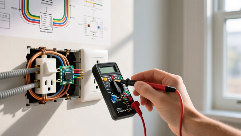
Once the physical installation is verified and the breaker is restored, it is time to measure the electrical characteristics. Set your Fluke 117 to V AC.
Test A: Line to Neutral (Hot to Neutral)
Insert the red probe into the shorter (hot) slot and the black probe into the longer (neutral) slot. Expected Reading: 118V to 122V (depending on local utility transformer tap settings). If you read significantly lower (e.g., 105V), you may have a high-resistance connection upstream or an overloaded shared neutral.
Test B: Line to Ground (Hot to Ground)
Insert the red probe into the hot slot and the black probe into the D-shaped ground hole. Expected Reading: Identical to Line-Neutral (118V–122V). If this reads 0V, you have an open ground. If it reads slightly higher than Line-Neutral (e.g., 120.5V vs 119.5V), this is normal and indicates a slight voltage drop on the neutral conductor under load.
Test C: Neutral to Ground
Insert the red probe into the neutral slot and the black probe into the ground hole. Expected Reading: 0.0V to 0.5V. Any reading above 1.5V indicates a shared neutral issue, an overloaded circuit, or a neutral-ground bond error at the subpanel.
Troubleshooting Matrix: Multimeter Readings
| Line-Neutral | Line-Ground | Neutral-Ground | Diagnosis & Required Action |
|---|---|---|---|
| 120V | 120V | 0V | Correct Wiring. Proceed to torque verification. |
| 120V | 0V | 0V | Open Ground. Check ground pigtail to metal box or grounding bar. |
| 120V | 120V | 120V | Open Neutral / Reversed Polarity. Hot and Neutral are swapped. |
| 0V | 0V | 0V | Open Hot. Breaker is off, or upstream wire nut has failed. |
| 40V-90V | 40V-90V | 0V | Phantom Voltage. Switch multimeter to LoZ mode to bleed ghost voltage. |
Step 4: Catching the "Bootleg Ground" Edge Case
A bootleg ground is a dangerous, deceptive DIY hack where a jumper wire is installed between the neutral terminal and the ground screw on the receptacle. This tricks standard $10 plug-in testers into showing a green "Correct" light, but it creates a severe shock hazard. If the neutral wire ever disconnects upstream, the metal chassis of any plugged-in appliance becomes energized at 120V.
How to Defeat a Bootleg Ground
Standard digital multimeters have high impedance (10 Megohms) and cannot easily detect a bootleg ground under no-load conditions. To expose this hazard:
- Use a solenoid voltage tester (like a Wiggy) or the LoZ setting on your Fluke 117.
- Measure between the Hot slot and the Ground slot.
- If a bootleg ground is present, the low impedance of the solenoid will draw current through the neutral jumper. If the circuit is GFCI-protected upstream, this will instantly trip the GFCI. If it is a standard breaker, you may see the voltage sag significantly, or you can physically remove the receptacle to spot the illegal copper jumper wire.
Step 5: NEC Torque Verification (110.14(D))
Since the 2017 NEC update, and heavily enforced in 2026 inspections, NEC 110.14(D) requires that terminations be torqued to the manufacturer's specified values using a calibrated tool. Hand-tightening is no longer code-compliant for new installations.
Standard Torque Specifications
For standard 15A and 20A commercial receptacles (e.g., Leviton 5362, Hubbell 5262), the manufacturer specifications are typically:
- 14 AWG Copper: 14 in-lbs (inch-pounds)
- 12 AWG Copper: 16 in-lbs (inch-pounds)
Set your Wiha torque screwdriver to the appropriate value. Tighten the terminal screw until the driver audibly clicks. This ensures the wire is compressed sufficiently to prevent thermal expansion from loosening the connection over years of heating and cooling cycles, without stripping the brass screw threads.
Final Box Dressing and Reassembly
Once electrical and mechanical verifications are complete, dress the wires into the box. Fold the bare copper ground wires into the back corners first, followed by the neutrals, and finally the hot wires. This prevents the ground wire from resting against the hot terminal screws, which can cause a dead short when the receptacle is pushed back into a metal box.
Secure the receptacle using the provided 6-32 mounting screws. If the drywall is uneven and the receptacle rocks, use OSHA-compliant plastic shims (like the Ideal Spacers) behind the mounting ears rather than over-tightening the screws, which can crack the nylon yoke and compromise the internal contact tension.
Summary
Knowing how to check electrical outlet wiring goes far beyond plugging in a basic tester. By utilizing a True-RMS multimeter with LoZ capabilities, verifying torque to NEC 110.14(D) standards, and actively hunting for deceptive edge cases like bootleg grounds, you ensure a safe, fire-resistant, and code-compliant installation that will reliably serve the end-user for decades.