
Understanding the "Blown" Electrical Outlet
In the electrical trade, the term "blown" is rarely used by professionals, but it is the most common phrase homeowners use to describe a failed receptacle. When you encounter a blown electrical outlet, you are typically facing one of three scenarios: a tripped circuit breaker due to a dead short, a tripped GFCI/AFCI mechanism, or physical thermal damage (melting and scorching) caused by a high-resistance connection. According to the U.S. Consumer Product Safety Commission (CPSC), loose or degraded connections inside receptacles are a leading cause of residential electrical fires, resulting in thousands of incidents annually.
If your outlet is physically melted, smells like burning plastic, or simply refuses to deliver power after resetting the breaker, the internal brass wipers or terminal screws have likely failed. In 2026, the National Electrical Code (NEC) strictly mandates the use of Tamper-Resistant (TR) receptacles and calibrated torque terminations for all replacements. This guide provides a master electrician’s step-by-step protocol for safely diagnosing, extracting, and replacing a failed 15-amp or 20-amp duplex receptacle.
Diagnostic Matrix: Why Did Your Outlet Fail?
Before grabbing a screwdriver, you must identify the root cause. Replacing an outlet without fixing the underlying fault will result in immediate failure or a severe fire hazard.
| Symptom | Probable Root Cause | Required Action |
|---|---|---|
| Dead outlet; breaker trips instantly upon reset | Dead short (Hot touching Ground/Neutral) or failed appliance | Unplug all devices; inspect wiring for pinched insulation before replacing. |
| Scorch marks on faceplate; melted plastic smell | "Backstabbed" push-in connections loosened over time, causing high-resistance arcing | Cut back damaged wire; replace outlet using side-wire screw terminations. |
| Outlet works intermittently when wiggled | Internal brass wiper fatigue or broken yoke | Replace the receptacle immediately; do not use push-in backwiring. |
| Reset button on outlet won't stay engaged | Internal GFCI sensor failure or upstream ground fault | Replace with a new 20A GFCI receptacle; verify line/load orientation. |
Required Tools and Materials (2026 Standards)
To ensure compliance with modern safety codes and prevent future thermal failures, you need the right tools. Do not rely on outdated methods.
- Voltage Tester: Fluke 2AC-II Non-Contact Voltage Tester (Approx. $35). Essential for verifying zero energy state.
- Torque Screwdriver: Klein Tools 32500 or WIHA 320P (Approx. $45-$60). The NEC Section 110.14(D) requires terminations to be tightened to the manufacturer's specified torque.
- Wire Strippers: Klein 11055 (Approx. $25). For clean copper scoring without nicking the conductor.
- Replacement Receptacle: Leviton 15A TR Duplex (Model R52-05320-WST) or Hubbell 20A TR (Model HBL5262). Expect to pay $3 to $6 per unit. Ensure it is marked "TR" (Tamper-Resistant).
Step-by-Step Replacement Guide
Step 1: Establish a Zero-Energy State (LOTO)
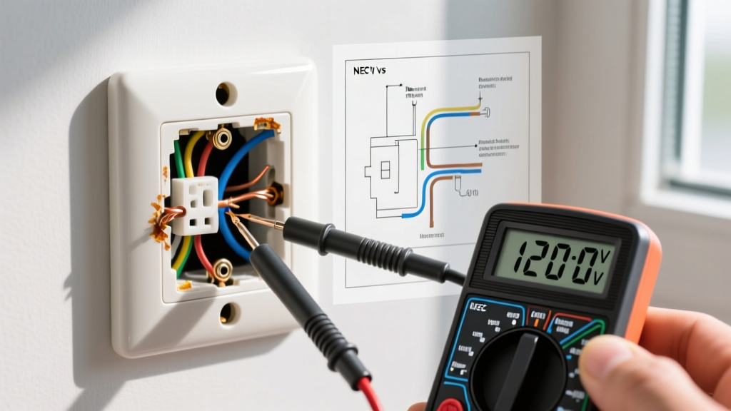
Never trust a wall switch to isolate power. Go to your main service panel and switch off the breaker controlling the circuit. The Occupational Safety and Health Administration (OSHA) strongly advocates for Lockout/Tagout (LOTO) procedures even in residential settings. Place a piece of electrical tape over the breaker switch to prevent a family member from accidentally flipping it back on while your hands are in the junction box. Verify the power is off by inserting the Fluke 2AC-II tester into both the top and bottom slots of the dead outlet, as well as a known live outlet to confirm the tester's battery is functional.
Step 2: Extract and Inspect the Failed Receptacle
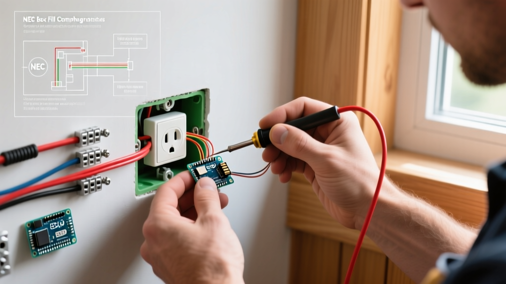
Remove the center 6-32 machine screw holding the faceplate. Next, remove the two 6-32 mounting screws securing the receptacle yoke to the drywall box. Gently pull the outlet out of the box. Critical Inspection Point: Look at the back of the outlet. If the wires are inserted into the small push-in holes (backstabbing), this is almost certainly why your outlet "blew." Backstabbed connections rely on a tiny internal spring that loosens under thermal cycling, leading to arcing and melting.
Step 3: Prep and Condition the Conductors
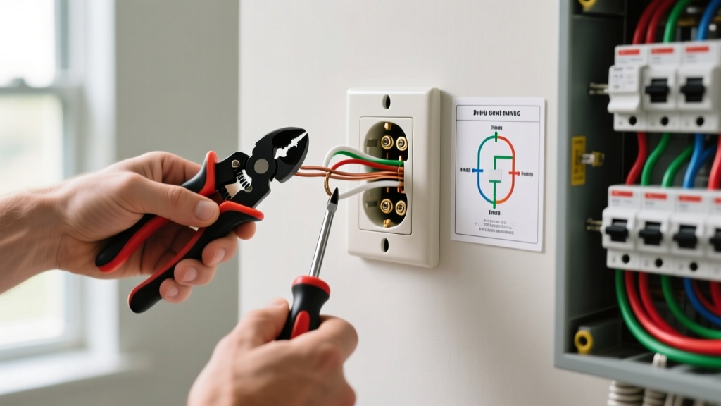
Using a flathead screwdriver, release the old wires. If the copper is blackened, pitted, or brittle from heat damage, you must cut it back to clean, shiny copper. Use your Klein 11055 wire strippers to strip exactly 5/8-inch of insulation from the wire ends. A 5/8-inch strip ensures the copper fully wraps around the terminal screw without exposing bare wire outside the screw head, which violates NEC clearance rules and risks short circuits.
Step 4: Terminate Using the "Shepherd's Hook" Method
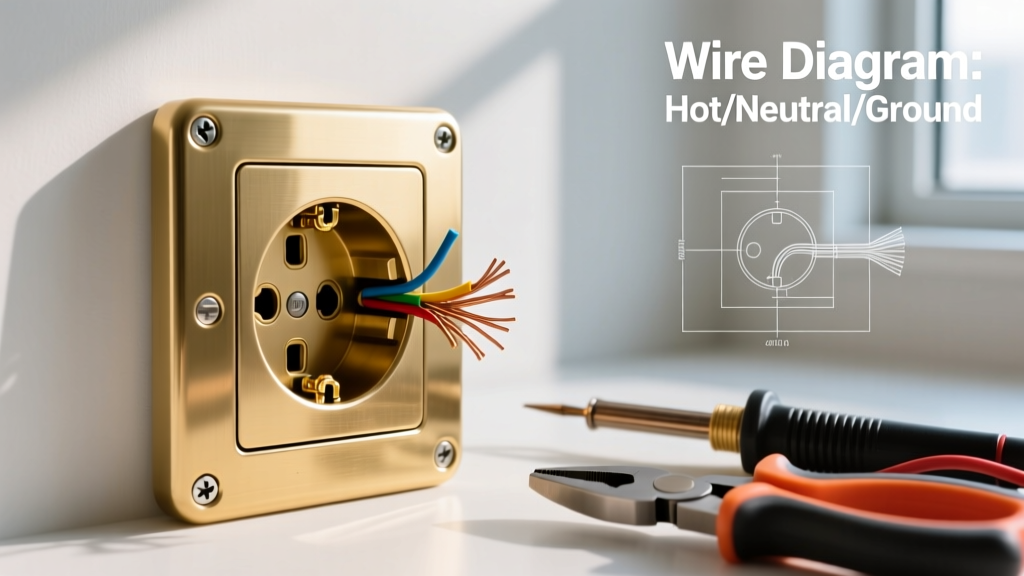
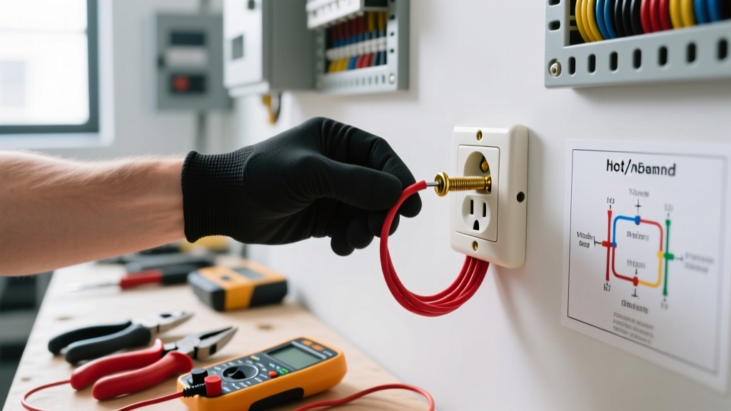
Bend the stripped wire ends into a tight "J" hook using the needle-nose pliers on your wire strippers. Hook the wire around the brass (hot) and silver (neutral) terminal screws in a clockwise direction. This ensures that tightening the screw pulls the wire loop tighter rather than pushing it out. The ground wire (bare or green) connects to the green grounding screw. Code Compliance: Use your torque screwdriver set to the manufacturer's specification—typically 14 in-lbs for standard 15A Leviton receptacles. This prevents under-tightening (which causes arcing) and over-tightening (which strips the brass threads).
Step 5: Mount, Dress, and Test
Carefully fold the wires into the back of the junction box in a "Z" pattern, pushing the ground wires to the very back, followed by the neutrals, and finally the hots. Seat the yoke flush against the drywall. If the box is recessed more than 1/4-inch into the wall, you must use plastic receptacle shims (spacers) to prevent the yoke from bending when you plug in a cord. Secure with the mounting screws, attach a new TR faceplate, remove the LOTO tape, and energize the breaker. Test with a standard 3-light receptacle tester to confirm correct wiring.
CRITICAL WARNING: Multi-Wire Branch Circuits (MWBC)
When you pull the outlet out, count the wires. If you see a black wire AND a red wire connected to the brass screws on opposite sides of the yoke, you have an MWBC (a shared neutral circuit). You MUST NOT break the metal fin on the neutral (silver) side. Breaking the neutral fin on an MWBC will place 240V across your 120V appliances, instantly destroying them and causing a massive fire. Furthermore, the National Fire Protection Association (NFPA) requires MWBCs to have a simultaneous disconnect (handle-tied breakers) at the panel. If you encounter this setup and are unsure, stop and call a licensed electrician.
GFCI vs. Standard Receptacle Identification
If the blown outlet has "Test" and "Reset" buttons, it is a Ground Fault Circuit Interrupter (GFCI). Replacing a GFCI is more complex than a standard duplex outlet. GFCIs feature two sets of terminals: LINE (incoming power) and LOAD (downstream protection). Connecting the incoming hot and neutral to the LOAD terminals will result in an outlet that appears to work but provides zero ground-fault protection, creating a lethal shock hazard in wet areas like kitchens, bathrooms, and garages. Always use the manufacturer's included line/load identification stickers and verify the power source with a voltage tester before connecting to the LINE terminals.
Final Thoughts on Outlet Longevity
The era of using $0.50 builder-grade receptacles and backstabbing them for speed is over. The combination of modern high-draw appliances and strict 2026 NEC torque requirements means that side-wiring with a calibrated torque screwdriver is the only acceptable method for replacing a blown electrical outlet. By investing the extra three minutes per termination to form proper shepherd's hooks and torque the screws to 14 in-lbs, you eliminate the high-resistance joints that cause 90% of all residential receptacle fires. Always prioritize TR-rated devices to protect children, and never bypass a tripping breaker by simply swapping the outlet without diagnosing the downstream fault.