
Introduction to Single Pole Dimmer Installations
Upgrading a standard toggle switch to a dimmer is one of the most rewarding DIY electrical projects you can tackle. It instantly improves the ambiance of a room and, according to the U.S. Department of Energy, dimming LED lights can extend their lifespan and reduce energy consumption. However, the foundation of a safe and functional installation lies in correctly interpreting the wiring diagram for dimmer switch single pole configurations. A single pole setup means one switch controls the light fixture from a single location, making it the most common residential scenario.
As of 2026, the market is dominated by advanced LED-compatible dimmers like the Lutron Diva LED+ (DVCL-153P) and smart options like the Leviton Decora Smart Wi-Fi (DW6HD). While these devices offer incredible features, their internal electronics require precise wiring. This beginner tutorial will decode the wiring process, provide actionable installation steps, and help you avoid the most common pitfalls that lead to flickering lights or tripped breakers.
Safety First: NEC Compliance
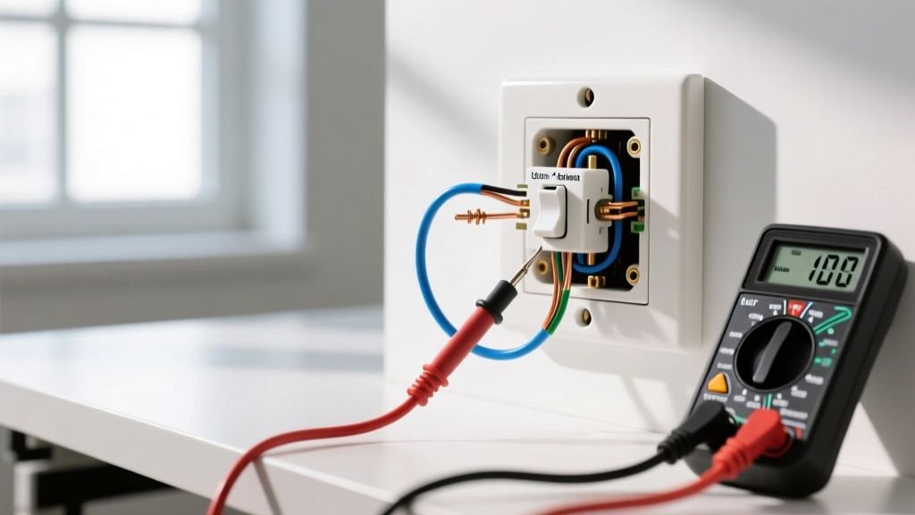
Before touching any wires, you must shut off power at the main circuit breaker. The National Fire Protection Association (NFPA) emphasizes that verifying the absence of voltage with a non-contact tester is the single most critical step in preventing electrical shock. Always test your tester on a known live circuit before and after checking the target switch.
Decoding the Wiring Diagram for Dimmer Switch Single Pole Circuits
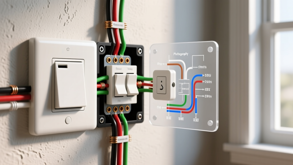
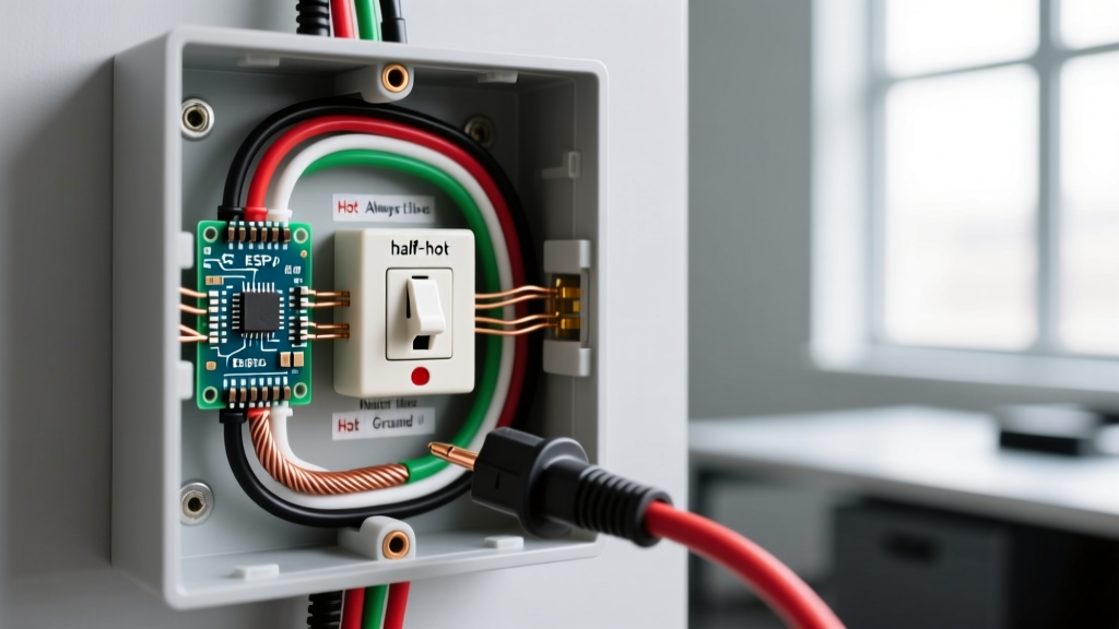
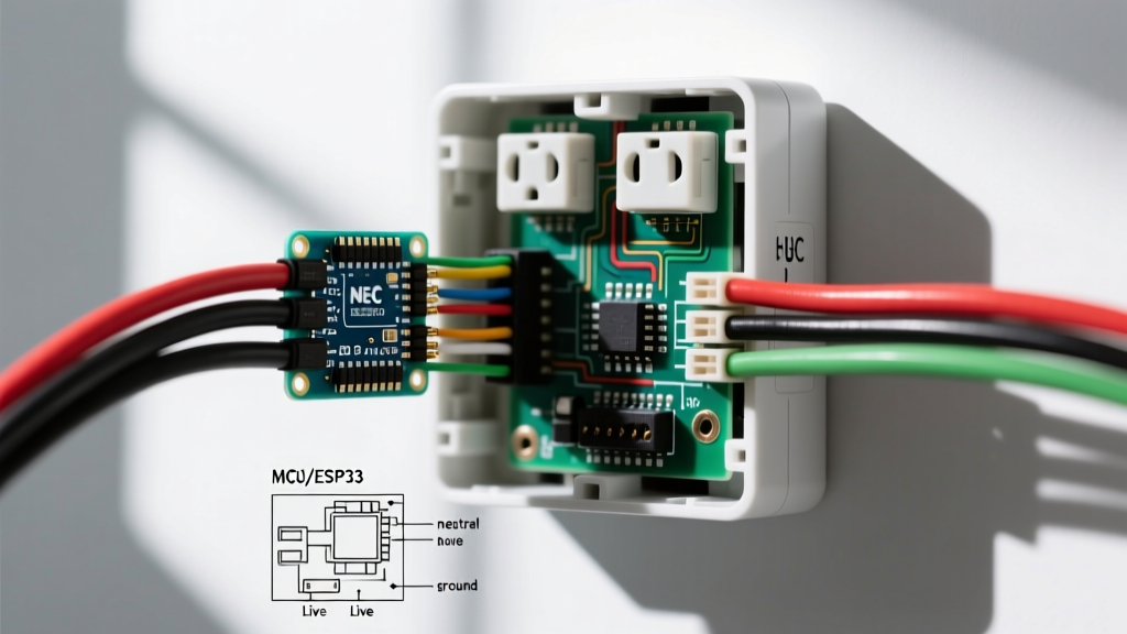
Unlike a simple mechanical toggle switch that merely breaks the hot wire, a modern dimmer is an electronic device. It requires a continuous path for current and, in the case of smart dimmers, a neutral wire to power its internal Wi-Fi or Zigbee radios. Understanding the mapping of your wall box wires to the dimmer's pigtails is essential.
| Wall Box Wire | Dimmer Pigtail / Terminal | Function & Notes |
|---|---|---|
| Bare Copper or Green | Green (Ground) | Safety ground. Required by NEC Article 404.9. Must be connected to the metal box if present. |
| White (Neutral Bundle) | White (Neutral) | Completes the circuit for smart dimmers. Standard analog dimmers (like basic TRIAC models) may not require this. |
| Black (Always Hot / Line) | Black (Line / Hot) | Brings 120V power from the breaker panel. Must be identified with a voltage tester before disconnecting the old switch. |
| Black or Red (Switched Hot) | Red or Blue (Load) | Carries the dimmed power up to the light fixture. |
Line vs. Load: The Beginner's Trap
In a traditional single pole toggle switch, the line (power in) and load (power out) wires are interchangeable. You can wire them backward, and the light will still work. This is not true for smart dimmers or advanced electronic dimmers. If you wire the load into the line terminal on a Leviton DW6HD, the internal microprocessor will not receive power, and the switch will remain dead. Always identify the 'Line' wire by turning the breaker on temporarily, testing the wires with a non-contact voltage tester, and marking the live wire with black electrical tape before turning the breaker back off.
Essential Tools and Material Costs (2026 Pricing)
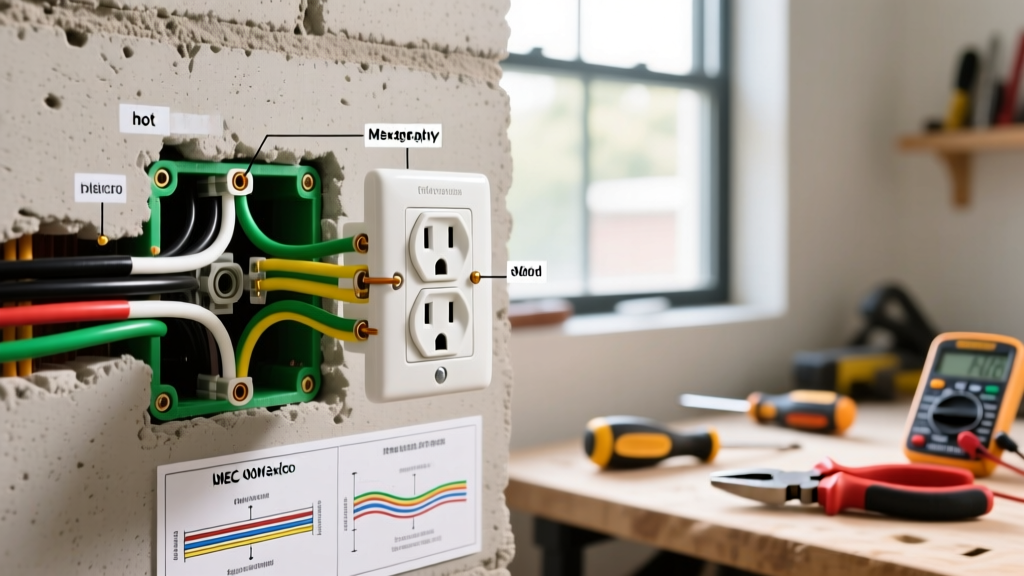
To execute this wiring diagram properly, you need the right tools. Relying on a flathead screwdriver and a kitchen knife is a recipe for damaged wire insulation and loose connections.
- Non-Contact Voltage Tester: Fluke 1AC-II or Klein Tools NCVT-2 (~$25 - $35). Essential for verifying a dead circuit.
- Wire Strippers: Klein Tools 11055 (10-20 AWG) (~$25). Ensures clean stripping without nicking the copper conductor, which can cause hotspots.
- Torque Screwdriver: Wiha 64500 or similar (~$40). NEC 110.14(D) requires terminals to be tightened to manufacturer specifications, typically 14 in-lbs for standard residential switches.
- Wire Connectors: Ideal In-Sure Push-In connectors or standard wire nuts (~$5 per pack). Push-ins are faster and provide consistent grip on 14 AWG and 12 AWG solid wire.
- The Dimmer Switch: Standard LED dimmers (e.g., Lutron Diva) cost $20-$30. Smart Wi-Fi dimmers range from $45-$65.
Step-by-Step Installation Flow
Follow this precise sequence to ensure your wiring diagram translates perfectly into physical reality.
Step 1: Preparation and Verification
- Turn off the 15A or 20A breaker controlling the room.
- Test the existing switch with your voltage tester to confirm power is off.
- Remove the faceplate and unscrew the existing toggle switch. Pull it out gently without disconnecting the wires yet.
- Test the exposed wires one more time to guarantee safety.
Step 2: Wire Identification and Prep
- Identify the Line (Hot) and Load wires. If unsure, use the temporary power-on testing method mentioned earlier.
- Disconnect the old switch.
- Inspect the wire ends. If the copper is nicked, deeply scratched, or oxidized, snip the end off and strip a fresh 3/4-inch of insulation using your wire strippers.
Step 3: Making the Connections
- Ground First: Connect the bare copper/green ground wire from the wall to the green ground pigtail on the dimmer using a wire nut or push-in connector.
- Neutral (If applicable): If installing a smart dimmer, connect the dimmer's white neutral pigtail to the bundle of white neutral wires in the back of the box. Do not connect it to the bare ground wire.
- Line and Load: Connect the wall's Line wire to the dimmer's Line terminal (usually black), and the wall's Load wire to the dimmer's Load terminal (usually red or blue).
- Torque: If using screw terminals instead of pigtails, wrap the wire clockwise around the screw and tighten to 14 in-lbs.
Step 4: Box Fill and Mounting
Dimmer switches have larger metal yokes and deeper bodies than standard toggles. According to NEC Article 314.16, you must ensure your electrical box has adequate volume. A standard single-gang box (18 cubic inches) is usually sufficient for one dimmer and standard wiring, but if you have multiple cables entering the box, you may need a deeper 'old work' box. Carefully fold the wires into the box, pushing the wire nuts into the back corners to make room for the dimmer's heat sink.
Advanced Insight: LED Compatibility and Dimming Curves
A perfectly wired dimmer will still fail if paired with the wrong light bulbs. Modern LEDs do not respond to voltage drops the way incandescent bulbs do; they rely on internal drivers. You must match the dimmer type to the LED driver type.
Expert Tip: Always check the Lutron LED Compatibility Tool before purchasing bulbs. Mixing a Forward Phase (TRIAC) dimmer with an LED bulb designed for Reverse Phase (ELV) will result in severe flickering, buzzing, and premature failure of the bulb's driver.
If your wiring diagram for dimmer switch single pole setups is correct but the lights buzz, you likely have a phase mismatch. Standard dimmers like the Lutron DVCL-153P are Forward Phase. If you are using low-voltage LED tape lights with an ELV transformer, you must purchase a specific Reverse Phase dimmer (like the Lutron DVELV-300P), which requires a different internal wiring configuration and often a dedicated neutral wire.
Troubleshooting Common Installation Failures
Even with a flawless wiring diagram execution, edge cases occur. Use this matrix to diagnose post-installation issues.
| Symptom | Probable Cause | Actionable Fix |
|---|---|---|
| Lights flicker at low dim levels | Dimmer low-end trim is set too low for the specific LED driver. | Adjust the low-end trim dial (usually a small physical slider on the side of the dimmer) upward until flickering stops. |
| Audible buzzing from the switch | Overloading the dimmer or using incompatible CFL/LED bulbs. | Verify total wattage. A 150W LED-rated dimmer can only handle roughly 10-15 standard LED bulbs. Reduce the load or upgrade to a higher capacity dimmer. |
| Smart dimmer won't connect to Wi-Fi | Neutral wire is not properly connected, or 5GHz network is being used. | Check the neutral wire nut connection. Ensure your router is broadcasting a 2.4GHz network, as most smart switches cannot see 5GHz bands. |
| Lights turn on but won't dim | Line and Load wires are reversed on a smart/electronic dimmer. | Turn off breaker, swap the Line and Load wires, and re-test. |
Frequently Asked Questions
Can I install a single pole dimmer without a ground wire?
Technically, older homes (pre-1960s) may lack a ground wire in the switch box. While some older dimmers function without it, the NEC strictly requires all new switch installations to be grounded. If your box is metal and grounded via conduit, you can attach the dimmer's ground pigtail to the metal box using a green grounding screw. If you have no ground path at all, you should consult a licensed electrician to upgrade the circuit or install a GFCI breaker to provide shock protection as an alternative safety measure.
Do I need a special dimmer for 3-way setups?
Yes. The wiring diagram for dimmer switch single pole configurations will not work if your light is controlled by two different switches. For a 3-way setup, you must purchase a specific 3-way dimmer kit (which often includes a companion toggle switch) and follow a completely different wiring schematic that utilizes the traveler wires.
Final Thoughts
Mastering the wiring diagram for dimmer switch single pole setups is about more than just matching wire colors; it is about understanding the flow of current, the requirements of modern LED electronics, and the safety standards that protect your home. By taking the time to identify your Line and Load wires, using a torque screwdriver for secure connections, and verifying LED compatibility, you ensure a professional-grade installation that will provide years of flawless, ambient lighting.