
The Anatomy of a Failing Receptacle
When dealing with a bad electrical outlet, understanding the underlying wiring diagram is the difference between a simple swap and a misdiagnosed circuit failure. A receptacle is not just a passive hole in the wall; it is a critical junction point where thermal cycling, mechanical stress, and electrical load interact. According to the National Fire Protection Association (NFPA), electrical distribution and lighting equipment, including failing receptacles and loose connections, remain a leading cause of residential structure fires.
Before replacing a dead or sparking outlet, you must map the fault to its exact origin. This guide utilizes standard NEMA 5-15R (15-Amp) and NEMA 5-20R (20-Amp) wiring diagrams to help you isolate whether the failure is at the terminal screws, the upstream junction box, or the breaker panel.
Standard Receptacle Wiring Diagram Breakdown
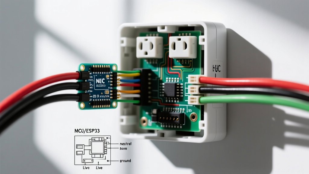
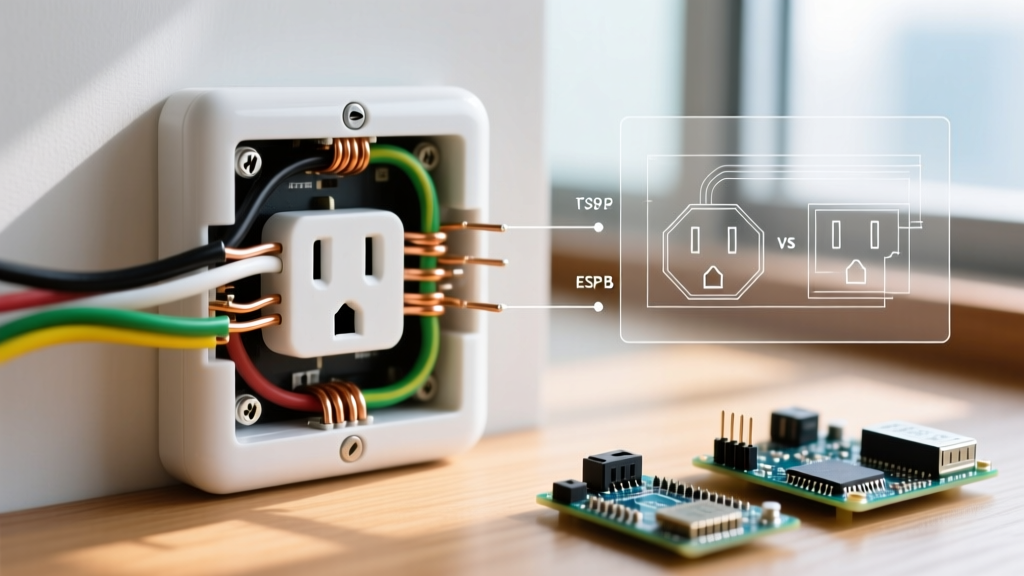
A standard 120-volt duplex receptacle features three primary connection zones. Misidentifying these zones is the most common cause of post-replacement failures, especially when upgrading to GFCI or smart receptacles.
- Line (Hot / Brass Screws): This is the incoming power from the breaker panel. The black (or red) wire connects here. In a standard wiring diagram, the hot wire routes through the brass-colored terminal screws.
- Neutral (Silver Screws): The white wire completes the circuit back to the panel. It connects to the silver terminal screws. An open neutral is a frequent culprit behind a bad electrical outlet that shows voltage on a non-contact tester but drops to zero under load.
- Ground (Green Screw): The bare copper or green insulated wire connects to the green grounding screw, providing a safe path for fault currents.
- Load Terminals (GFCI/AFCI Only): Standard outlets do not have load terminals. However, if your bad outlet is a GFCI, the Load terminals (usually covered by a yellow warning tape) feed downstream outlets. Reversing Line and Load is a catastrophic wiring error that leaves downstream devices unprotected.
Diagnostic Matrix: Symptoms vs. Wiring Faults
Use this diagnostic matrix to correlate the physical behavior of your bad electrical outlet with specific wiring diagram failures.
| Observed Symptom | Multimeter Reading | Likely Wiring Fault | Diagram Reference Point |
|---|---|---|---|
| Completely Dead | 0V Hot-to-Neutral | Open Hot wire or tripped breaker | Line / Brass Screw |
| Intermittent Power | Fluctuating 110-120V | Backstabbed push-in connection failure | Push-in Terminal (Rear) |
| Shocks when touching appliance | 0V, but chassis reads hot | Open Ground or Reversed Polarity | Green Screw / Silver Screw |
| Downstream outlets dead, this one works | 120V Hot-to-Neutral | Broken daisy-chain pigtail or loose wire nut | Secondary Brass/Silver Screws |
| GFCI won't reset or test | 120V present | Line and Load terminals reversed | GFCI Load Terminals |
Step-by-Step Multimeter Testing Protocol
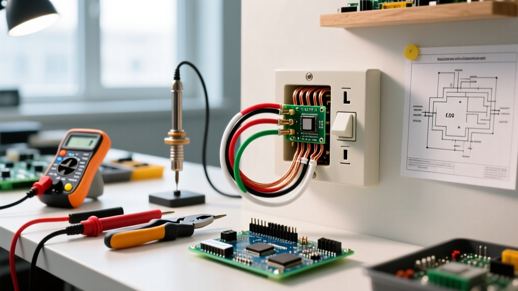
To accurately diagnose a bad electrical outlet, abandon cheap plug-in neon testers and use a True-RMS digital multimeter, such as the Fluke 117 or the Klein Tools MM400. Plug-in testers cannot measure voltage drop under load, which is where most hidden thermal failures occur.
Step 1: No-Load Voltage Test
Set your multimeter to AC Voltage (V~). Insert the red probe into the smaller slot (Hot) and the black probe into the larger slot (Neutral). A healthy 120V circuit should read between 114V and 126V. Next, test Hot to Ground (small slot to the round D-shaped hole). If Hot-to-Neutral reads 120V, but Hot-to-Ground reads 0V, you have an open ground fault, rendering the outlet unsafe for surge protectors and metal-chassis appliances.
Step 2: The Voltage Drop (Load) Test
This is the ultimate test for a bad electrical outlet suffering from internal corrosion or loose terminal screws. Plug a high-draw appliance (like a 1500W space heater or a hair dryer) into the top receptacle. While the appliance is running, measure the voltage at the bottom receptacle. If the voltage drops by more than 3% to 5% (e.g., dropping from 120V to 110V or lower), the internal brass contacts are degraded, or the upstream wire connections are suffering from high resistance. The outlet must be replaced immediately.
The Danger of Backstabbed Connections
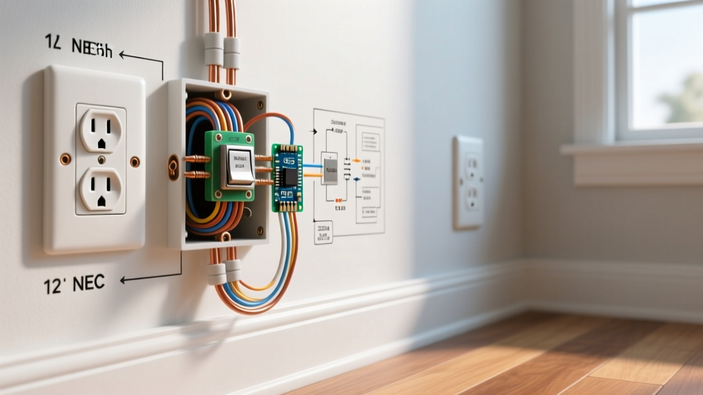
When reviewing the wiring diagram of a failed outlet, you will frequently find wires inserted into the rear push-in holes rather than wrapped around the side terminal screws. This practice, known as "backstabbing," relies on a tiny internal brass spring to grip the 14 AWG or 12 AWG wire.
Expert Insight: Over years of thermal cycling—heating up when drawing current and cooling down when idle—the internal spring loses its tension. This creates a high-resistance connection that generates immense heat, melting the plastic housing and causing arcing. As of 2026, professional electricians universally condemn backstabbing for any circuit drawing more than a few amps.
The Fix: Always use the side terminal screws. For maximum safety and NEC compliance, use a torque screwdriver (such as the Milwaukee 48-22-2901) set to the manufacturer's specification. For most modern Leviton and Hubbell receptacles, the required torque is exactly 14 in-lbs. This prevents both loose connections and stripped screws.
Edge Case: Aluminum Wiring Failures
If your home was built between 1965 and 1972, a bad electrical outlet might not be the fault of the device itself, but the wiring. Aluminum wire expands and contracts at a different rate than copper, leading to "creep" and eventual loosening under standard brass terminal screws. Furthermore, aluminum oxidizes rapidly when exposed to air, creating a highly resistive layer that causes fires.
According to the U.S. Consumer Product Safety Commission (CPSC), homes with original aluminum branch wiring are significantly more likely to experience outlet fires. If you discover silver-colored wire, you cannot use a standard receptacle. You must use a CO/ALR (Copper/Aluminum Revised) rated outlet, such as the Leviton 1259, or pigtail the aluminum wire to copper using AlumiConn connectors before attaching it to a standard device.
Replacement Guide: Choosing the Right Receptacle
When your diagnostic confirms the device itself is the point of failure, selecting the correct replacement is vital. Standard receptacles cost between $1.50 and $3.00, but upgrading to commercial-grade or tamper-resistant models is highly recommended.
- Standard Residential (15A): Leviton T5262 (Tamper-Resistant). Priced around $3.50. Features heavy-duty internal contacts and a thermoplastic housing that resists impact and heat.
- Commercial/Industrial (20A): Hubbell 5362 (20A TR). Priced around $7.00. Built with glass-filled nylon and massive brass contact surfaces designed for high-cycle environments like workshops or kitchens.
- GFCI Protection: Leviton SmartlockPro 15-Amp GFCI. Priced around $18.00. Features a self-testing mechanism that automatically cuts power if the internal ground-fault circuitry fails, eliminating the false sense of security provided by older GFCI models.
Final Safety and Code Compliance Checks
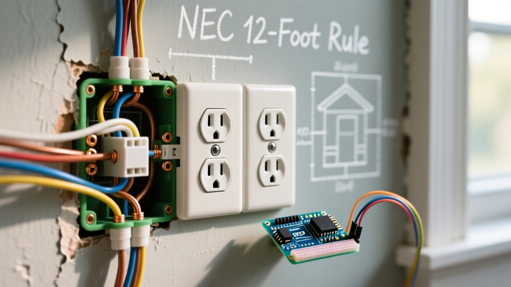
Before closing up the electrical box, ensure your wiring adheres to the latest National Electrical Code (NEC) standards. Verify that the grounding wire is securely bonded to the metal box (if applicable) using a green grounding screw or pigtail. Ensure no more than three wires are under a single terminal screw, and that the bare copper ground wire does not touch the silver neutral screws. Finally, confirm that the outlet faces the correct orientation (ground pin up or down is a regional debate, but consistency across the room is key for aesthetic and code inspection purposes). By treating every bad electrical outlet as a diagnostic puzzle rather than a simple swap, you ensure the long-term safety and reliability of your home's electrical infrastructure.