
How to Add an Electrical Outlet to an Existing Outlet: The Complete Guide
Understanding how to add an electrical outlet to an existing outlet is one of the most practical and cost-effective DIY electrical projects you can undertake. Often referred to as 'daisy chaining' or extending a circuit, this process involves tapping into the power source of an existing receptacle to feed a new one. While the concept is straightforward, executing it safely requires strict adherence to the National Electrical Code (NEC), proper wire gauge matching, and precise termination techniques.
In this comprehensive 2026 guide, we will walk you through the exact step-by-step installation process, from calculating box fill capacity to terminating wires on a tamper-resistant receptacle. Whether you are adding an outlet behind a wall-mounted TV or extending power to a new home office desk, this guide ensures your installation is safe, code-compliant, and built to last.
CRITICAL SAFETY WARNING: Never extend a circuit that is already near its maximum amperage capacity. Overloading a 15-amp or 20-amp branch circuit is a leading cause of residential electrical fires. Always verify the existing circuit's load before adding new receptacles.
Tools and Materials Checklist
Using the right tools prevents damaged conductors and loose connections, which are primary culprits behind arc faults. Below is the professional-grade gear required for this installation.
| Category | Item / Model Recommendation | Purpose |
|---|---|---|
| Wire | Southwire 14/2 or 12/2 NM-B Romex | Must match the existing circuit's gauge and amperage. |
| Receptacle | Leviton R62-05320-000 (15A Tamper-Resistant) | NEC mandates tamper-resistant (TR) outlets in all living areas. |
| Box | Carlon B114R (1-Gang Old Work Box, 14 cu in) | Non-metallic retrofit box for existing drywall. |
| Strippers | Klein Tools 11055 Wire Strippers | Ensures clean insulation removal without nicking the copper. |
| Connectors | WAGO 221-413 Lever Nuts or Ideal 72B Wire-Nuts | For secure pigtailing and grounding connections. |
| Tester | Fluke 1AC-II Non-Contact Voltage Tester | Verifies the circuit is completely de-energized. |
Pre-Installation: Code Checks and Box Fill Calculations
Before cutting into your drywall, you must verify two critical NEC requirements: circuit loading and box fill capacity.
1. Match the Wire Gauge and Breaker Size
Open your electrical panel and identify the breaker controlling the existing outlet. If it is a 15-amp breaker, the existing wire is likely 14 AWG, and you must use 14/2 NM-B cable for the extension. If it is a 20-amp breaker, the existing wire is 12 AWG, and you must use 12/2 NM-B cable. Never install 14 AWG wire on a 20-amp circuit; the breaker will not trip before the smaller wire melts and catches fire.
2. Calculate Box Fill Capacity (NEC Article 314)
Every electrical box has a maximum volume limit measured in cubic inches. When you add a second cable to an existing outlet box, you introduce new conductors that consume volume. According to NFPA NEC guidelines, each 14 AWG conductor requires 2.0 cubic inches of space, while 12 AWG requires 2.25 cubic inches. A standard single-gang old-work box (usually 14 to 18 cubic inches) can typically handle the original two cables plus one new outgoing cable, but you must verify the box's stamped volume rating to avoid overcrowding, which causes heat buildup.
Step-by-Step Installation Process
Step 1: Kill the Power and Verify
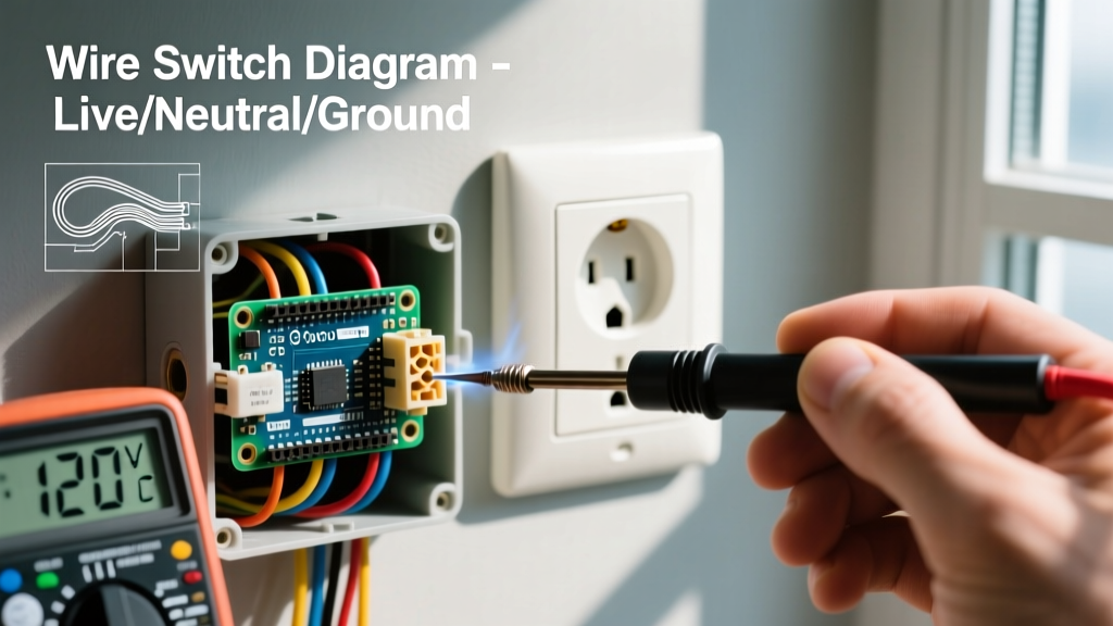
Turn off the corresponding breaker at the main panel. Plug a lamp or use your Fluke non-contact voltage tester into the existing outlet to confirm the power is completely dead. Test both the top and bottom receptacles, as they may be on different circuits or split-wired.
Step 2: Cut the Drywall and Mount the New Box
Use a stud finder to ensure no wooden studs or metal plates are behind your chosen location. Trace the outline of your Carlon old-work box on the drywall and cut it out using a drywall keyhole saw. Feed the new 14/2 or 12/2 NM cable through the back of the box, leaving about 8 inches of slack. Insert the box into the wall and tighten the mounting screws until the plastic flippers pull the box flush against the drywall.
Step 3: Run the Cable Between Boxes
Feed the new cable from the new box to the existing box. If the walls are open or you have attic/basement access, route the cable through the framing. If you are fishing the cable through a closed wall, use fiberglass fish tape and flexible drill bits to navigate the top and bottom plates. Ensure the cable is secured within 12 inches of the box using cable staples if exposed in a basement or attic.
Step 4: Prep and Terminate the Existing Outlet
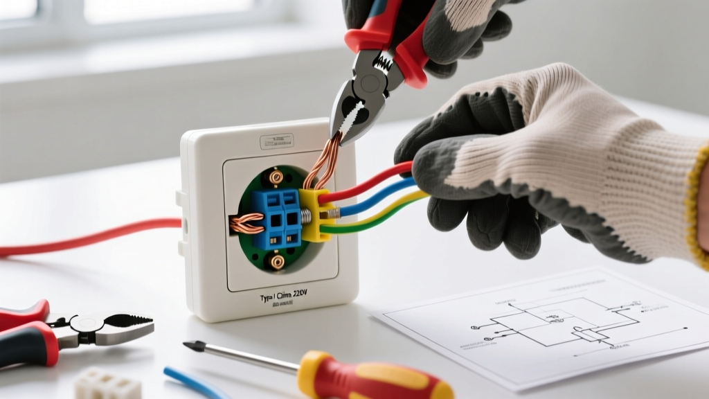
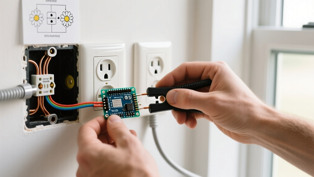
Remove the existing receptacle from the box. You will now have the original line/load wires and your newly added cable. Strip exactly 3/4 inch of insulation from the black and white wires using the gauge-specific holes on your Klein strippers. Do not use the push-in backstab terminals. Backstab connections are notorious for loosening over time, leading to arcing. Always use the side screw terminals.
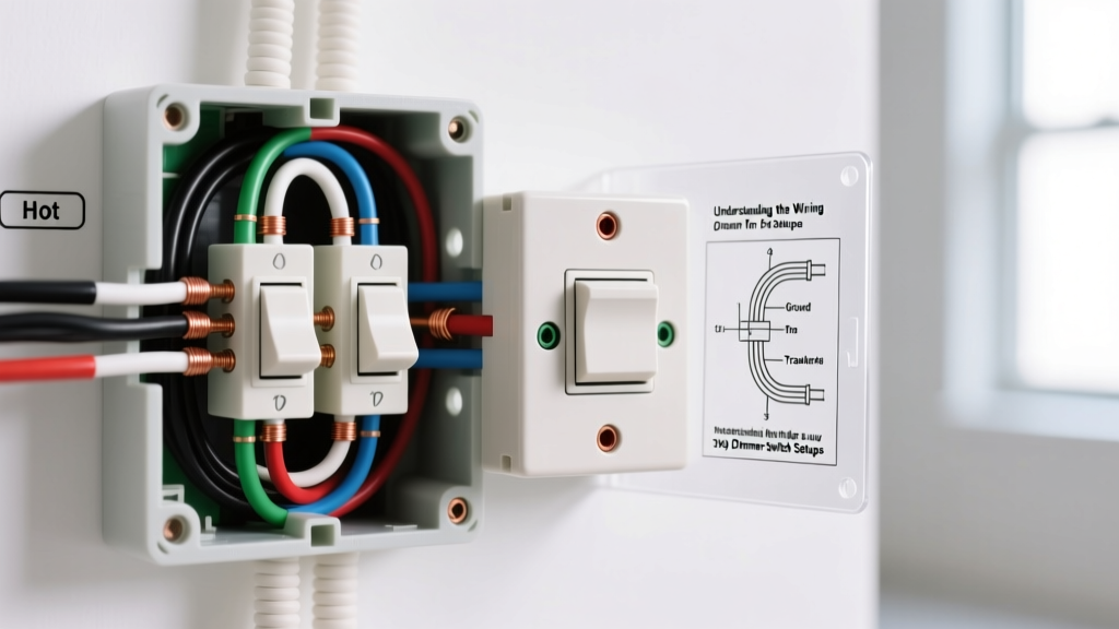
Pigtailing Method: If the existing outlet's screws are already occupied, you must 'pigtail' the wires. Use a WAGO lever nut or wire nut to connect the existing black wire, the new black wire, and a 6-inch black pigtail wire. Connect the pigtail to the brass screw on the receptacle. Repeat for the white neutral wires (silver screw) and bare ground wires (green screw).
Step 5: Wire the New Receptacle
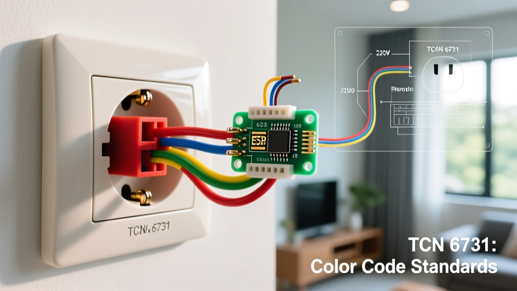
At the new outlet location, strip the wires and form a clockwise hook at the end of each conductor. The clockwise hook ensures that as you tighten the screw, the loop pulls tighter rather than pushing out. Connect the black wire to the brass screw, the white wire to the silver screw, and the bare copper to the green ground screw. Tighten the screws firmly. The CPSC recommends ensuring no bare copper is exposed outside the terminal and that the insulation is not pinched under the screw head.
Step 6: Final Testing
Carefully fold the wires into the boxes using a Z-fold pattern (ground in back, neutral in middle, hot in front). Screw the receptacles to the boxes, attach the faceplates, and restore power at the breaker. Use a 3-prong receptacle tester to verify correct wiring. The tester should show two solid yellow lights (indicating correct polarity and ground).
Edge Case: Extending from a GFCI Outlet
If the existing outlet you are tapping into is a Ground Fault Circuit Interrupter (GFCI), you have a critical decision to make regarding downstream protection. GFCI receptacles have two sets of terminals: LINE and LOAD.
- LINE Terminals: Connect to the power source from the panel.
- LOAD Terminals: Protect downstream outlets.
If you connect your new outlet's wires to the LOAD terminals of the existing GFCI, the new outlet will also be GFCI-protected. This is highly recommended for kitchens, bathrooms, garages, and outdoor extensions. If you connect to the LINE terminals (via pigtailing), the new outlet will have standard protection only. Always check local codes, as the 2023/2026 NEC requires GFCI protection in specific damp or hazardous locations.
Daisy Chaining vs. Home Run Wiring
When planning your electrical layout, it is vital to understand when daisy chaining is appropriate versus when a home run is necessary.
| Feature | Daisy Chain (Extending Existing) | Home Run (New Circuit to Panel) |
|---|---|---|
| Cost | Low ($15 - $30 in materials) | High ($150 - $300+ including breaker and long wire runs) |
| Labor/Time | 1 - 2 Hours | 4 - 8 Hours (requires panel work and extensive fishing) |
| Best Application | Adding a single outlet for a TV, lamp, or phone charger. | High-draw appliances, dedicated home office circuits, or kitchen countertops. |
| Code Limitation | Limited by the existing breaker's total amperage capacity. | Provides full, dedicated amperage for the new location. |
Troubleshooting Common Installation Errors
Even experienced DIYers can run into issues when extending circuits. Here is how to diagnose the most common failure modes:
- Reversed Polarity: If your tester shows the rightmost light and the middle light (instead of the left and middle), you have swapped the hot and neutral wires. Turn off the breaker and ensure the black wire is on the brass screw and the white is on the silver.
- Open Ground: If the third light on the tester fails to illuminate, your ground connection is loose or missing. Check the wire nut connection in the back of the box and ensure the bare copper is firmly secured to the green screw.
- AFCI Breaker Tripping: Modern AFCI (Arc Fault Circuit Interrupter) breakers are highly sensitive. If the breaker trips immediately upon restoring power, you likely have a loose neutral connection, a nicked wire insulation touching the metal box, or a shared neutral from another circuit. Inspect all terminations for tightness and stray wire strands.
Authoritative References
For further reading on electrical safety and code compliance, consult the following resources:
- National Fire Protection Association (NFPA) - Codes and Standards
- U.S. Consumer Product Safety Commission (CPSC) - Electrical Safety Center
By following these precise steps and respecting the physical limits of your branch circuit, you can safely add an electrical outlet to an existing outlet, enhancing your home's functionality while maintaining a rigorous standard of electrical safety.