
The 2026 Case for Upgrading Dual-Location Switches
Controlling a single light fixture from two separate locations—such as the top and bottom of a staircase or dual entrances to a hallway—is a fundamental convenience in modern home design. However, the mechanical switches facilitating this have a finite lifespan. If you are researching electrical wiring 2 way light switch circuits, you are likely dealing with failing contacts, aesthetic mismatches, or a desire to integrate smart home automation.
Before proceeding, a critical terminology clarification is required for global accuracy. In the UK, Australia, and New Zealand, this dual-location setup is universally known as a 2-way switch. In North America (US and Canada), this exact same circuit topology is referred to as a 3-way switch. This guide utilizes the international '2-way' terminology to match your search intent, while providing North American equivalents to ensure complete technical clarity.
Safety Warning: Working with mains electricity carries a risk of fatal shock or fire. Always isolate the circuit at the main distribution board (consumer unit) and verify zero voltage with a CAT III rated multimeter before touching any terminals. If you are unsure, hire a licensed electrician.
Terminal Anatomy & Regional Terminology
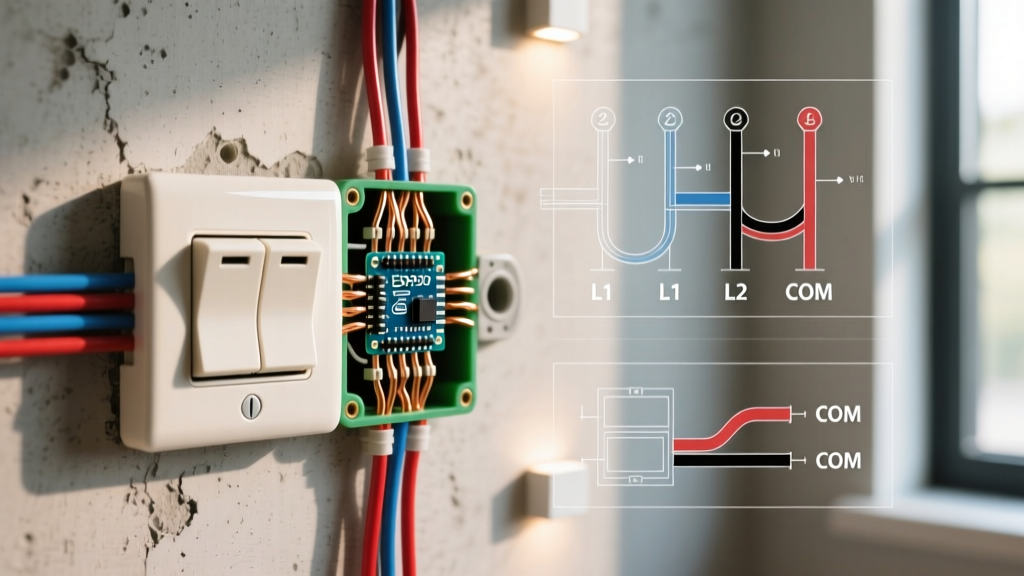
Understanding the terminal designations is the most common failure point for DIY replacements. Miswiring the 'strappers' (travelers) will result in a circuit that only works from one location, or worse, creates a dead short.
| Region | Switch Name | Common Terminal | Traveler 1 | Traveler 2 | Standard Wire Colors (Active) |
|---|---|---|---|---|---|
| UK / AUS / NZ | 2-Way | COM | L1 | L2 | Brown (or Red in pre-2006) |
| US / Canada | 3-Way | COM (Dark Screw) | Traveler 1 (Brass) | Traveler 2 (Brass) | Black (Line/Load), Red/White (Travelers) |
Pre-Upgrade Diagnostics: Identifying Failure Modes
Why replace the switch? In 2026, the most common reasons for upgrading a 2-way circuit extend beyond simple cosmetic updates. Look for these specific failure modes:
- Carbon Pitting & Arcing: Over 15+ years, the internal brass contacts degrade. If your switch feels 'mushy' or makes a distinct buzzing sound when toggled, the contacts are pitted. This increases electrical resistance, generating excess heat and potentially melting the faceplate.
- LED Flickering (Ghosting): Older mechanical switches paired with modern low-wattage LED bulbs can cause ghosting. While usually a smart-switch issue, failing mechanical contacts can also cause micro-interruptions that make cheap LED drivers strobe.
- Loose Strapper Connections: If the light only operates from one of the two switch locations, the traveler (strapper) wire on the L1/L2 terminals has likely backed out of the terminal block due to thermal expansion and contraction cycles.
The Replacement Protocol: Step-by-Step
Follow this precise methodology to ensure a safe and code-compliant upgrade. For this guide, we assume you are upgrading to a premium mechanical switch (e.g., MK Logic Plus or Lutron Claro) or preparing the circuit for a smart relay.
Step 1: Isolation and Verification
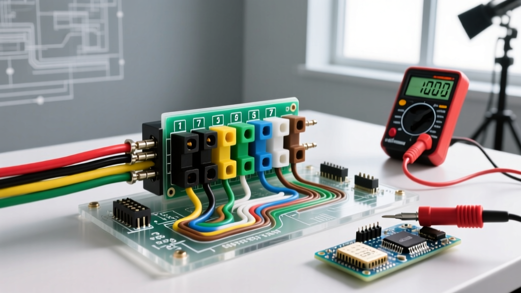
Switch off the specific MCB (Miniature Circuit Breaker) or fuse for the lighting circuit. Do not rely solely on the wall switch being in the 'off' position. Use a CAT III multimeter to test between the COM terminal and earth/ground. The reading must be exactly 0.0V. As emphasized by the Electrical Safety Foundation International (ESFI), verifying dead circuits is the single most important step in preventing arc flashes.
Step 2: The 'Photo & Label' Method
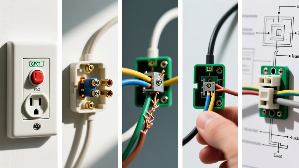
Before loosening a single screw, take a high-resolution, well-lit photograph of the existing wiring. In a 2-way setup, the COM terminal holds either the permanent live (line) or the switched live (load) going to the fixture. The L1 and L2 terminals hold the interconnecting traveler wires. If you mix the COM and L1 wires, the circuit will fail to operate correctly from both locations.
Step 3: Terminal Extraction and Preparation
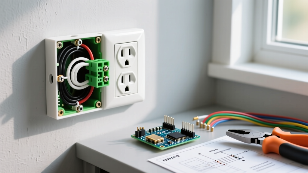
Loosen the terminal screws. If the copper wire ends are heavily oxidized (dark brown/black) or frayed, snip them back and re-strip exactly 12mm of insulation using precision wire strippers. For 1.5mm² (or 14 AWG) solid copper wire, ensure no bare copper is exposed outside the terminal block once inserted.
Step 4: Torque and Termination
Insert the wires into the new switch. COM goes to COM, L1 to L1, L2 to L2. Tighten the terminal screws. Professional electricians use a torque screwdriver set to 0.4 Nm to 0.5 Nm for standard switch terminals. Overtightening can crush the copper and cause cold-flow creep, leading to loose connections and fire hazards over time. Adherence to proper termination torque is a key requirement in both the IET Wiring Regulations (BS 7671) and the NFPA 70 (National Electrical Code).
Smart Switch Upgrade Matrix (2026 Edition)
If your goal is to upgrade your electrical wiring 2 way light switch circuit to a smart home ecosystem, you must replace the mechanical switches with smart relays or smart switch pairs. The physical 2-way wiring is often bypassed or repurposed in these setups.
| Brand / Model (2026) | Protocol | Neutral Required? | Avg. Price (USD) | Best Application |
|---|---|---|---|---|
| Shelly Plus 1PM | Wi-Fi / Bluetooth | No (with bypass) | $28 | UK/EU retrofits behind existing switches |
| Lutron Caseta Diva | Clear Connect RF | No | $75 | US/Canada rock-solid reliability |
| Aeotec Nano Dimmer 800 | Z-Wave 800 Series | Yes | $62 | Hub-based ecosystems (Home Assistant) |
| Sonoff ZBMINI-L2 | Zigbee 3.0 | No | $18 | Budget multi-way smart upgrades |
How Smart 2-Way Wiring Differs
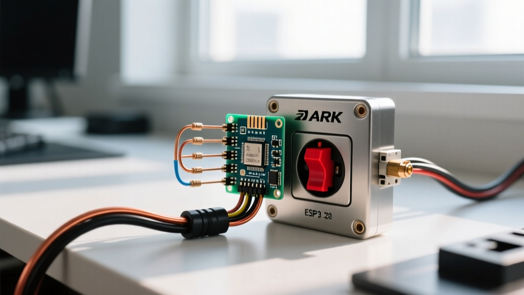
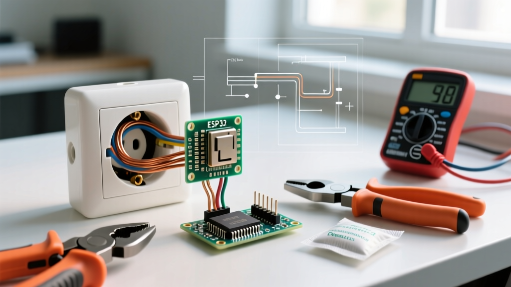
When upgrading to smart relays like the Shelly Plus 1PM or Sonoff ZBMINI-L2, you typically install the relay at the light fixture or the primary switch backbox. The existing physical L1 and L2 traveler wires are often capped off and abandoned in the wall, while the secondary wall switch is rewired to act as a low-voltage momentary trigger or replaced entirely by a wireless battery-powered remote (like the Lutron Pico). This eliminates the voltage drop issues inherent in long physical traveler wire runs.
Edge Cases & Troubleshooting
The 'Missing Neutral' Dilemma
In many homes built before 1990, the switch backbox only contains the line, load, and travelers—no neutral wire. Standard smart switches require a neutral to power their internal Wi-Fi or Zigbee radios. Solution: Use 'no-neutral' specific models (like the Lutron Caseta or Shelly Plus 1PM). If using a Shelly, you must install a 0.1µF / 275VAC X2 suppression capacitor across the live and neutral at the light fixture itself to provide a return path for the micro-current, preventing the LED bulb from flashing when the smart switch is in the 'off' state.
Deep Backbox Requirements
Upgrading from a standard 16mm drywall box to a smart relay setup requires physical space. Smart relays are typically 39mm deep. You must upgrade your wall boxes to a minimum of 35mm deep (preferably 47mm) to safely accommodate the relay, the wire nuts/Wago connectors, and the physical switch mechanism without crushing the cables, which violates bend-radius safety codes.
Final Compliance and Testing
Once the upgrade is complete and the faceplate is secured, restore power at the distribution board. Test the circuit from both locations. If you installed a smart relay, initiate a pairing sequence via your hub or app and verify that the physical switch toggle state perfectly syncs with the digital app state. Properly executed electrical wiring 2 way light switch upgrades not only modernize your home's aesthetic and functionality but significantly reduce the risk of electrical fires caused by aging, high-resistance mechanical contacts.