
The Hidden Dangers of Poor Harness Architecture
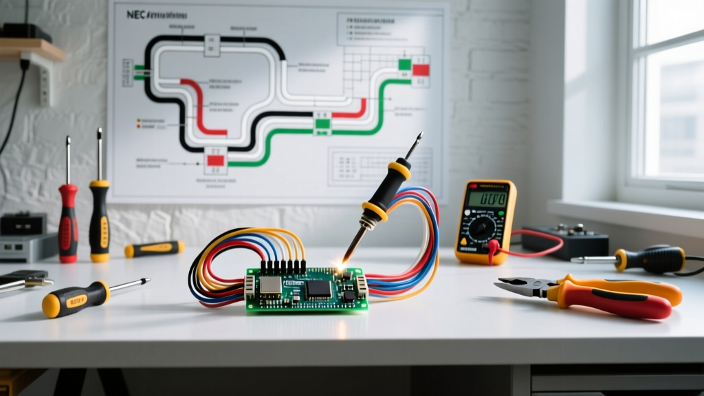
When engineers and custom builders address wiring harness electrical safety, the focus often lands exclusively on overcurrent protection. However, the vast majority of harness-related thermal events, voltage drops, and catastrophic shorts originate from improper conductor derating, substandard crimp terminations, and aggressive routing geometries. A wiring harness is not merely a collection of wires; it is a highly integrated thermal and mechanical system.
According to the OSHA Electrical Safety Standards, improper wiring methods and degraded insulation are leading contributors to industrial electrical fires. In mobile and off-highway applications, vibration-induced chafing and capillary action in unsealed crimps cause intermittent faults that standard fuses cannot detect. This guide details the exact specifications, tooling requirements, and routing protocols necessary to build a fault-tolerant harness in 2026.
Conductor Selection and Bundle Derating
The most frequent safety failure in custom harness design is ignoring thermal derating. When wires are bundled tightly together, they cannot dissipate heat effectively. A 16 AWG wire rated for 15 amps in free air may safely carry only 9 amps when bound in a 10-circuit harness.
Insulation Chemistry: PVC vs. XLPE
For high-reliability applications, abandon standard PVC (Polyvinyl Chloride) wire. PVC insulation begins to soften and melt at approximately 105°C, and it emits toxic hydrochloric gas when burned. Instead, specify Cross-Linked Polyethylene (XLPE) variants such as GXL, TXL, or SXL. These insulations withstand continuous temperatures up to 125°C (and spikes to 150°C), offering superior resistance to abrasion and chemical exposure.
Bundle Derating Matrix
Use the following derating factors based on the Wiring Harness Manufacturer's Association (WHMA) guidelines and standard aerospace practices to calculate true ampacity:
| Number of Conductors in Bundle | Derating Factor (Multiplier) | Effective Ampacity (Example: 16 AWG / 15A Base) |
|---|---|---|
| 1 (Single wire in free air) | 1.00 | 15.0 Amps |
| 2 - 4 wires | 0.80 | 12.0 Amps |
| 5 - 8 wires | 0.65 | 9.75 Amps |
| 9 - 15 wires | 0.50 | 7.5 Amps |
| 16+ wires | 0.40 | 6.0 Amps |
Always size your overcurrent protection device (OCPD) based on the derated ampacity, not the free-air rating.
The Science of the Crimp: Beyond the Pliers
A crimp termination is a cold-weld process. If the wire barrel is not compressed to the exact specified geometry, the joint will suffer from high electrical resistance. Under load, this resistance generates heat, leading to thermal runaway and melted connectors.
Mandatory Tooling and Pull-Test Standards
Discard generic hardware store crimpers. Professional harness assembly requires ratcheting hand tools calibrated to specific wire and terminal cross-sections. For standard open-barrel terminals, the Molex 63811-1000 (approx. $380) or the TE Connectivity CERTI-CRIMP series are industry benchmarks. These tools feature a ratchet mechanism that prevents the jaws from opening until the exact crimp force and geometry are achieved.
Per IPC/WHMA-A-620 standards, every crimp must pass a mechanical pull test. Below are the minimum pull-force requirements for common AWG sizes:
- 22 AWG: 15 lbf (67 N)
- 18 AWG: 30 lbf (133 N)
- 16 AWG: 40 lbf (178 N)
- 14 AWG: 50 lbf (222 N)
- 12 AWG: 60 lbf (267 N)
Sealing Against Capillary Action
In mobile or outdoor environments, moisture will wick through the stranded wire via capillary action, eventually corroding the terminal from the inside out. To prevent this, use adhesive-lined, dual-wall heat shrink tubing (such as Raychem NTFR or 3M MDT). When heated, the inner thermoplastic layer melts and flows into the strand interstices, creating a hermetic seal that blocks moisture migration entirely.
Routing Geometries and Abrasion Protection
The National Electrical Code (NEC) Article 300.4 provides strict guidelines for protecting conductors from physical damage. While originally written for building wiring, the mechanical principles are critical for harness routing in custom vehicles, control panels, and machinery.
Bend Radius Limitations
Bending a wire too sharply work-hardens the copper strands, leading to micro-fractures that increase resistance and eventually snap under vibration. The minimum bend radius (MBR) must be strictly adhered to:
- Unshielded Wire: Minimum bend radius of 3x the outer diameter (OD) of the wire.
- Shielded / Coaxial Cable: Minimum bend radius of 6x to 8x the OD to prevent shield deformation and impedance shifts.
- Flat Ribbon Cable: Never fold flat cable at a 90-degree crease; use a sweeping loop.
Chafing and Pass-Through Protection
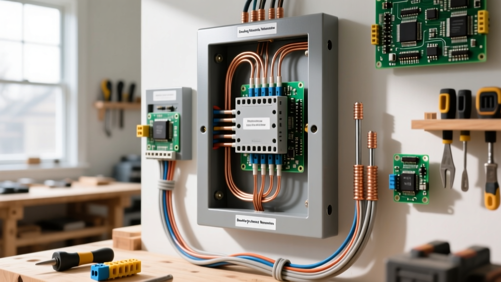
Virtually all harness failures in automotive and industrial applications occur at bulkhead pass-throughs or where the harness rests against a chassis edge. Never route a raw harness through a sheet metal hole. You must use elastomeric pass-through grommets (e.g., TE Connectivity DEUTSCH molded boots). If the harness must cross a sharp metal edge, install a U-channel nylon edge protector or use a rigid corrugated split-loom. For high-heat areas near exhaust manifolds, wrap the harness in Techflex F6 fiberglass sleeving, rated for continuous 1000°F exposure.
Overcurrent Protection and Grounding Architecture
A wiring harness is only as safe as its weakest circuit protection node. Proper fuse placement and grounding topology are non-negotiable.
Expert Rule of Thumb: The overcurrent protection device (fuse or breaker) must be located as close to the power source as physically possible. In 12V/24V DC mobile applications, the fuse must be within 18 inches of the battery positive terminal. If a short occurs in the unfused section between the battery and the fuse, the battery will dump thousands of amps into the wire, instantly vaporizing the copper and igniting the insulation.
Star Grounding vs. Daisy Chaining
Never daisy-chain high-current grounds. If a 20A motor and a 5A sensitive ECU share a single daisy-chained ground wire, a voltage drop across the shared path will introduce noise into the ECU or cause it to reset. Instead, utilize a Star Grounding Architecture. Route all ground wires back to a single, centralized bus bar that is bonded to the chassis or main negative terminal with a heavily oversized cable (typically 2 AWG or larger). This ensures that heavy transient loads do not corrupt the reference voltage of low-current control circuits.
Troubleshooting Common Harness Failure Modes
Even with meticulous assembly, harnesses can degrade. Recognizing the physical symptoms of failure modes allows for proactive maintenance before a catastrophic short occurs.
- Discolored Connector Housings: A brown or melted plastic cavity indicates a "dry crimp" or terminal mismatch. The high resistance at the crimp joint is generating excessive I²R heat. Cut back the wire and re-crimp using a calibrated ratcheting tool.
- Green/White Crust on Terminals: This is galvanic corrosion, often caused by joining dissimilar metals (e.g., copper wire to aluminum bus bars) without dielectric grease, or a failure in the heat-shrink seal allowing electrolyte ingress.
- Intermittent Sensor Dropouts: Often caused by "wire barrel insulation crimp" errors, where the crimp tool was set too tight and severed the outer copper strands beneath the insulation jacket. The wire passes a visual inspection but fails under mechanical vibration.
Final Safety Audits
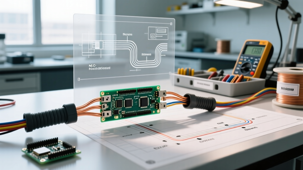
Before energizing any newly assembled wiring harness electrical system, perform a continuity and isolation test using a digital multimeter. Verify that no adjacent circuits share unintended continuity, and confirm that the resistance of any power-to-ground path (with the load disconnected) reads infinite (OL). By adhering to strict derating matrices, utilizing calibrated crimp tooling, and enforcing rigorous routing clearances, you transform a simple bundle of wires into a highly reliable, fail-safe electrical nervous system.