
Understanding Electric Meter Wiring: The Boundary of Responsibility
When planning a major home electrical upgrade, adding a solar array, or replacing an aging main panel, understanding electric meter wiring is a critical first step. The electric meter is the literal and legal boundary between the utility company's power grid and your home's private electrical system. As of 2026, with the widespread adoption of high-draw appliances like Level 2 EV chargers and all-electric heat pumps, residential service upgrades from 100A to 200A (or even 320A continuous/400A class) are at an all-time high.
CRITICAL SAFETY & LEGAL DISCLAIMER: The utility company exclusively owns and wires the "line side" (the incoming power from the street) and the physical meter itself. Homeowners and licensed electricians are only permitted to wire the "load side" (the meter socket base, service entrance conductors, and main breaker panel). Never break a utility seal or attempt to wire the line-side lugs. Doing so carries a severe risk of fatal arc flash and violates municipal and utility regulations.
This guide focuses on the homeowner and electrician's domain: preparing the meter socket, sizing the service entrance conductors, establishing the grounding electrode system, and ensuring the infrastructure is ready for the utility's final connection and smart meter installation.
The Anatomy of the Meter Socket Base
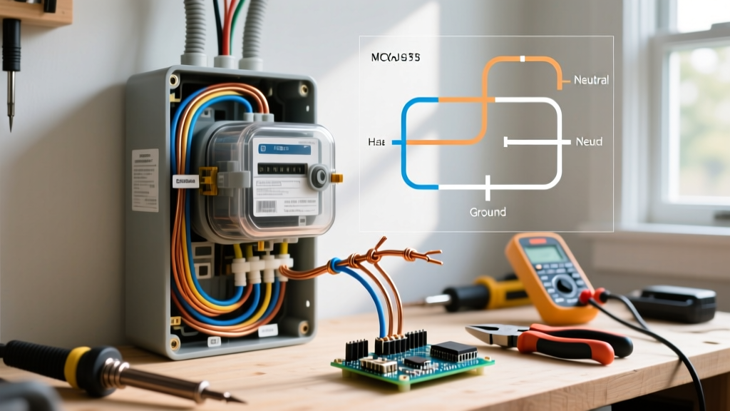
The meter socket (or meter pan) is the customer-owned enclosure that houses the utility's meter. For standard North American residential 120/240V split-phase systems, electric meter wiring relies on a 4-jaw meter socket. These four jaws connect to:
- Line 1 (L1): Incoming 120V phase from the utility transformer.
- Line 2 (L2): Incoming 120V phase (180 degrees out of phase with L1, yielding 240V across both).
- Load 1 & Load 2: Outgoing feeds to the home's main service panel breaker bus.
- Neutral Bus: A continuous, unbonded (in the socket) neutral bar that carries the unbalanced current and serves as the return path.
For modern 200-amp residential installations, a highly common and utility-approved model is the Milbank U4127-XL-8-500 or the Siemens W0542L11200CU. These enclosures feature heavy-duty aluminum or copper busbars, a 500 kcmil maximum wire capacity, and a hinged cover for easy utility access. When selecting a socket, always verify your local utility's "Green Book" or service installation manual, as some utilities mandate specific bypass lever configurations or ring-type versus ringless designs.
NEC Code Requirements and Conductor Sizing
Electric meter wiring is strictly governed by National Fire Protection Association (NFPA) NEC Article 230. Specifically, NEC 310.12(A) outlines the minimum conductor sizes for single-phase, 120/240V, 3-wire dwelling service entrance conductors. Because residential loads are highly diversified, the NEC allows specific sizing that differs from standard commercial ampacity tables.
| Service Rating | Copper Conductor (THHN/XHHW) | Aluminum Conductor (XHHW-2) | Typical 2026 Home Application |
|---|---|---|---|
| 100 Amps | #4 AWG | #2 AWG | Older homes, small additions, basic sheds |
| 150 Amps | #1 AWG | #1/0 AWG | Standard 3-bed homes built pre-2010 |
| 200 Amps | #2/0 AWG | #4/0 AWG | Modern standard, central HVAC, basic EV charging |
| 320 Amps (400A Class) | #350 kcmil | #600 kcmil | Luxury homes, multi-EV, all-electric appliance packages |
Note: While #4/0 AWG Aluminum (often sold as 4-4-4-2 AL SER cable) is the undisputed industry standard for 200A residential service upgrades due to its cost-effectiveness, you must ensure the meter socket lugs are properly rated and treated for aluminum wire.
Step-by-Step: Preparing the Meter Base for Utility Connection
Before the utility crew arrives to drop the service wires and install the smart meter, the site must be 100% prepared. Here is the professional workflow for electric meter wiring prep:
- Mounting Height and Clearance: Most utilities require the center of the meter socket to be mounted between 5 feet and 6 feet above final grade. Furthermore, NEC 110.26 mandates a clear working space of at least 30 inches wide and 36 inches deep in front of the meter and panel.
- Pulling the SER Cable: Service Entrance Round (SER) cable is pulled from the main panel up through the conduit or directly into the meter socket's bottom hub. For a 200A service, 4-4-4-2 Aluminum SER is standard. Leave at least 18 to 24 inches of extra wire inside the socket to allow for proper stripping and routing.
- Wire Stripping and Anti-Oxidant Treatment: Strip the insulation precisely to the length of the lug barrel. Because aluminum wire oxidizes and expands/contracts differently than copper, you must apply an anti-oxidant compound like Ideal Noalox or Burndy Penetrox-E to the exposed aluminum strands before inserting them into the lugs. This prevents galvanic corrosion and high-resistance hot spots.
- Torque Verification: The 2023 and 2026 NEC cycles heavily emphasize verified torque. Use a calibrated inch-pound torque wrench or torque screwdriver to tighten the lugs to the manufacturer's exact specifications (typically between 150 and 250 in-lbs for 4/0 AWG wire). Loose neutral lugs are the leading cause of catastrophic residential electrical fires.
Grounding and Bonding: The Electrode System
A vital, often misunderstood component of electric meter wiring is the Grounding Electrode System (GES). The neutral bus in the meter socket is not bonded to the enclosure (the bonding occurs at the first point of disconnect, usually the main breaker panel). However, the meter socket enclosure itself must be grounded.
According to NEC Article 250, a 200A service utilizing #4/0 AWG aluminum service conductors requires a minimum #4 AWG Copper Grounding Electrode Conductor (GEC). This bare copper wire must run continuously from the panel's neutral/ground bus to the grounding electrodes. In modern 2026 construction, a Ufer Ground (a concrete-encased electrode utilizing at least 20 feet of #4 AWG bare copper or 1/2-inch rebar in the foundation) is mandatory in most jurisdictions, supplemented by two 8-foot copper-clad ground rods driven 6 feet apart as a backup.
The Shift to Smart Meters and Solar Net Metering
The physical electric meter has evolved from a spinning electromechanical disc to an Advanced Metering Infrastructure (AMI) smart meter. According to the U.S. Energy Information Administration (EIA), over 75% of U.S. residential meters are now smart meters capable of two-way RF communication with the utility.
For homeowners adding solar PV systems, electric meter wiring becomes more complex. The U.S. Department of Energy (DOE) notes that net metering requires a bidirectional smart meter. If your solar array exceeds certain utility thresholds (often 15kW to 20kW), the utility may require a specialized meter socket with provisions for external Current Transformers (CTs). These CTs clamp around the main service conductors to accurately measure solar export versus grid import. When prepping a meter base for solar, ensure you purchase a socket with a bypass lever and adequate physical clearance for the utility's CT loops.
Common Failure Modes and Edge Cases
Even with professional installation, specific edge cases can cause electric meter wiring to fail prematurely. Be vigilant regarding the following:
- Water Ingress via Top Hubs: If your service mast (the pipe coming out of the top of the meter socket) is not sealed with a proper neoprene hub seal and silicone, rainwater will travel down the service drop wires directly into the meter socket, corroding the busbars. Always use a weatherhead and drip loop.
- Thermal Expansion of Aluminum: If the electrician fails to torque the lugs to spec or skips the Noalox paste, the aluminum wire will slowly creep out of the lug over years of thermal cycling (heating under load, cooling at night). This creates an arc fault on the line-side of the main breaker, meaning the main breaker cannot trip to protect it.
- Undersized Service Masts: For overhead electric meter wiring, the service mast must withstand the physical tension of the utility's drop wires. NEC 230.28 requires the mast to be of adequate strength. Standard 1.5-inch rigid galvanized steel conduit is the minimum for most utility spans exceeding 100 feet.
By understanding the strict division of labor between the utility and the homeowner, adhering to NEC ampacity tables, and utilizing modern torque and anti-oxidant protocols, you ensure your home's service entrance is safe, code-compliant, and ready for the electrical demands of the future.