
Why Standard Switches Fail with High-Draw Fans
When installing high-amperage ventilation, industrial exhaust, or heavy-duty cooling fans, direct switching through a standard wall toggle or low-voltage thermostat is a critical failure point. A typical 16-inch industrial pedestal fan or automotive radiator fan can draw anywhere from 15A to 30A on startup due to inrush current. Standard residential switches are generally rated for 15A resistive loads, not inductive motor loads. Over time, the arcing caused by breaking an inductive circuit will pit and weld the switch contacts, leading to overheating or fire.
The solution is electromagnetic isolation. By wiring an electric fan with relay components, you separate the high-current load circuit from the low-current control circuit. As of 2026, with the rise of smart-home integrations and low-voltage PWM thermostat outputs, utilizing a relay is no longer just best practice—it is mandatory for protecting sensitive control boards. According to the National Fire Protection Association (NFPA) guidelines on motor circuits, proper overcurrent protection and switching isolation must be strictly adhered to for inductive loads.
Bill of Materials: Exact Part Numbers & Specifications
Sourcing the correct components prevents premature failure. Below is a professional-grade Bill of Materials (BOM) for a standard 12V DC or 120V AC fan relay setup, scaled for a 30A continuous draw. Pricing reflects early 2026 market averages.
| Component | Recommended Model / Spec | Function | Est. Cost |
|---|---|---|---|
| Power Relay | Littelfuse RC Series 40A SPDT (or Bosch 0332014150) | Switches high current to the fan motor. | $12.50 |
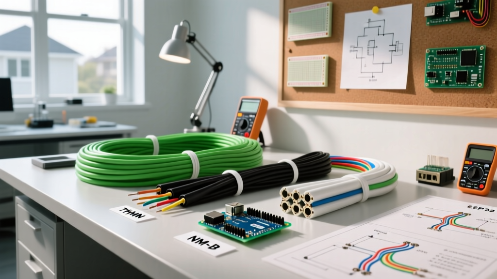
| Load Wire | 10 AWG THHN Stranded Copper | Carries main power from source to relay to fan. | $0.85/ft |
| Trigger Wire | 18 AWG MTW (Machine Tool Wire) | Carries low-current signal from switch to relay coil. | $0.35/ft |
| Fuse & Holder | Bussmann ATC 30A Blade & Inline Holder | Protects load circuit from short circuits. | $4.20 |
| Flyback Diode | 1N4007 Rectifier Diode | Dissipates inductive kickback voltage to protect switch. | $0.10 |
| Terminals | 3M Highland Vinyl-Insulated Ring (12-10 AWG) | Secure mechanical connection to relay posts. | $0.25/ea |
Required Tooling for Reliable Terminations
A relay setup is only as reliable as its physical connections. Vibration and thermal cycling will loosen poorly crimped terminals, leading to resistance heating. Invest in the following tools:
- Wire Strippers: Klein Tools 11063 (10-22 AWG). Features a precision shear that avoids nicking copper strands, which reduces wire ampacity.
- Crimper: Klein Tools 30055 or Titan 11520. A ratcheting crimper ensures the terminal barrel is deformed to the exact MIL-SPEC density required for a gas-tight connection.
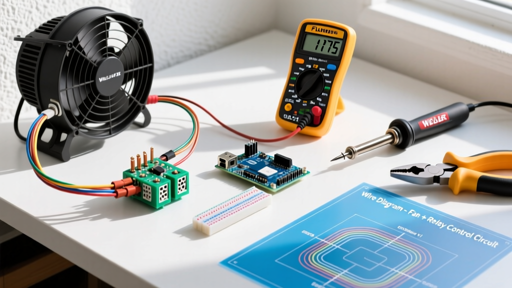
- Multimeter: Fluke 117 True-RMS. Essential for verifying coil voltage and checking for parasitic voltage drops across the load circuit.
- Heat Shrink Tubing: 3/16-inch and 1/4-inch dual-wall adhesive-lined shrink tube. The inner adhesive melts to form a waterproof seal over the crimp barrel.
Execution: Wiring an Electric Fan with Relay Step-by-Step
Standard automotive and industrial relays use the DIN 72552 numbering system. Understanding this pinout is critical before cutting any wire.
The 5-Pin Relay Pinout Breakdown
- Pin 30 (Common): Main power IN from the battery or breaker panel.
- Pin 87 (Normally Open): Power OUT to the electric fan. (Closes when coil is energized).
- Pin 85 (Coil Ground): Ground connection for the internal electromagnet.
- Pin 86 (Coil Power): Trigger power IN from your switch, thermostat, or ECU.
- Pin 87a (Normally Closed): Unused in standard fan applications; leave insulated and capped.
Step-by-Step Wiring Flow
- Isolate Power: Disconnect the main power source. Verify zero voltage at the source using your Fluke 117.
- Wire the Load Circuit (High Current): Run 10 AWG wire from your main power source through the Bussmann 30A inline fuse holder to Pin 30. Run a second 10 AWG wire from Pin 87 directly to the positive terminal of the electric fan. Ground the fan motor chassis to a clean, bare-metal ground point.
- Wire the Trigger Circuit (Low Current): Run 18 AWG wire from your control switch to Pin 86. Connect Pin 85 to a reliable chassis or system ground.
- Install the Flyback Diode: This is the most skipped step by amateurs. Solder or crimp a 1N4007 diode across Pins 85 and 86. Critical: The silver stripe on the diode MUST point toward Pin 86 (the positive trigger side).
- Test and Seal: Reconnect power. Activate the switch. The relay should audibly click, and the fan should spin. Apply heat shrink to all exposed solder joints and crimp barrels.
Edge Cases: Flyback Voltage and Coil Chatter
When wiring an electric fan with relay setups, two specific electrical phenomena frequently cause system failures if ignored.
1. Inductive Flyback Voltage
A relay coil is an inductor. When you turn off the trigger switch, the magnetic field collapses, inducing a massive reverse voltage spike (often exceeding 200V). Without a flyback diode, this spike arcs across your trigger switch contacts, destroying solid-state thermostats and microcontrollers instantly. For an in-depth physics breakdown of this phenomenon, refer to the All About Circuits guide on Electromechanical Relays.
2. Coil Chatter from Voltage Drop
If your trigger wire run exceeds 15 feet using 18 AWG wire, resistance will cause a voltage drop. If the voltage at Pin 86 falls below 75% of the coil's rated voltage (e.g., dropping below 9V on a 12V system), the relay will 'chatter'—rapidly opening and closing. This arcs the main contacts on Pin 30 and 87, welding them together and causing the fan to run continuously. Solution: For trigger runs longer than 15 feet, upgrade the trigger wire to 16 AWG or 14 AWG to mitigate resistance.
Troubleshooting Matrix
| Symptom | Probable Cause | Diagnostic Action |
|---|---|---|
| Relay clicks, but fan does not spin. | Undersized load wire, blown fuse, or bad fan ground. | Check voltage at fan positive terminal while relay is engaged. Should be within 0.5V of source. |
| Relay gets excessively hot. | High resistance at Pin 30/87 terminals due to poor crimping. | Inspect crimps. Re-crimp using a ratcheting tool and apply dielectric grease. |
| Trigger switch melts or smart-thermostat fries. | Missing or reversed flyback diode across coil pins. | Verify 1N4007 diode orientation (stripe to Pin 86). Replace damaged switch. |
| Fan runs continuously even when switch is off. | Main contacts (30 & 87) have welded together from arcing. | Disconnect power immediately. Replace relay and install proper snubber/diode. |
Safety Protocols and Code Compliance
Adhering to electrical codes is non-negotiable when dealing with motor loads. OSHA electrical safety guidelines and NEC Article 430 (Motors, Motor Circuits, and Controllers) dictate that motor circuits must be protected against both short circuits and prolonged overloads. While the inline ATC fuse protects against dead shorts, continuous running fans in enclosed spaces should also utilize a thermal overload protector integrated into the fan motor housing. Always ensure your relay is mounted in a well-ventilated, dry area, away from direct exhaust heat, to maintain the integrity of the internal copper coil insulation.
Pro-Tip for 2026 Installations: If you are integrating this fan relay with a modern smart-home hub (like Home Assistant or a Shelly relay module), ensure the smart module is rated for the specific inrush current of your fan. When in doubt, use the smart module to trigger the 18 AWG coil circuit of the heavy-duty mechanical relay detailed above, preserving your expensive smart electronics.