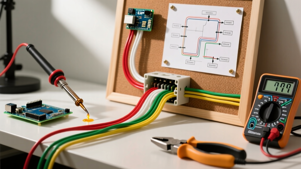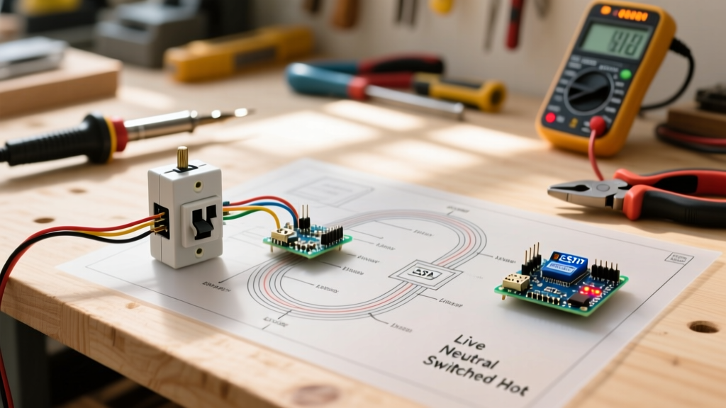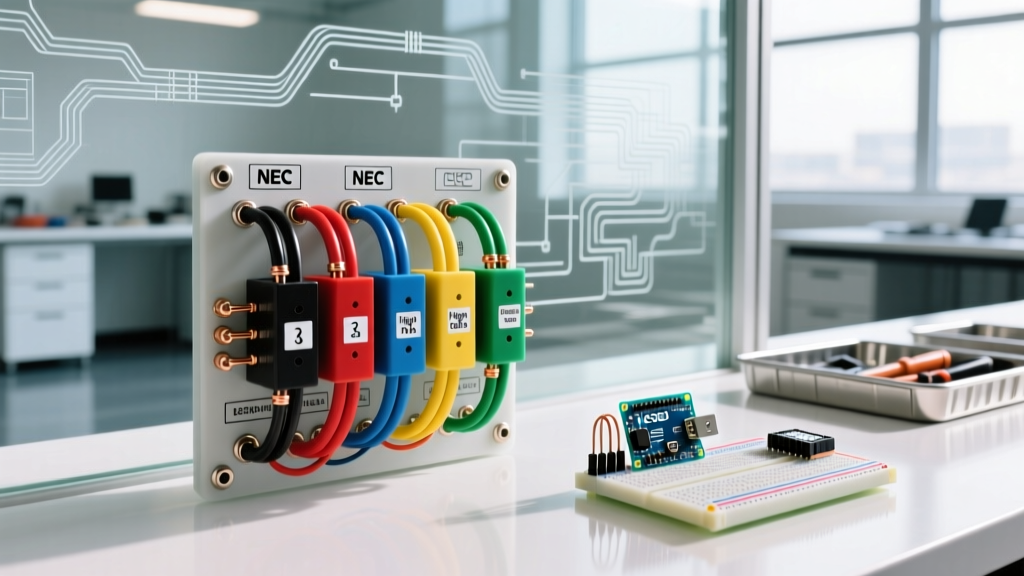

Why Color Codes Are Your First Line of Defense
When opening a junction box, panelboard, or disconnect switch, the insulation colors on THHN/THWN-2 conductors or the individual wires within NM-B (Romex) cables serve as your primary visual indicators of circuit function. However, treating the NFPA NEC guidelines as mere suggestions—or assuming previous electricians followed them—is a leading cause of arc flashes, equipment destruction, and fatal electrocutions. Understanding the standardized colors in electrical wiring is not just about passing an inspection; it is the foundational bedrock of electrical safety.
CRITICAL SAFETY RULE: Never trust wire color alone. Insulation fades, previous DIYers make dangerous substitutions, and manufacturing defects occur. Always verify a circuit is de-energized using a properly rated CAT III or CAT IV voltage tester before making physical contact with any conductor.
Standard Residential AC Wiring Colors (NEC Article 200 & 250)
In standard 120/240V single-phase residential and light commercial systems, the National Electrical Code (NEC) strictly dictates the identification of grounded (neutral) and grounding conductors, while allowing some regional flexibility for ungrounded (hot) conductors. Below is the definitive matrix for standard branch circuit wiring.
| Conductor Function | NEC Mandated Colors | Prohibited Colors | Common Wire Types |
|---|---|---|---|
| Ungrounded (Hot) | Black, Red, Blue (or any color except white, gray, green) | White, Gray, Green, Bare | THHN, NM-B, MC |
| Grounded (Neutral) | White, Gray | Black, Red, Blue, Green | THHN, NM-B, MC |
| Equipment Ground | Bare Copper, Green, Green with Yellow Stripe | White, Gray, Black, Red | Bare Copper, THHN |
Note on Re-identification: NEC Article 200.7(C) allows a white or gray wire to be used as an ungrounded (hot) conductor in specific scenarios, such as a switch loop or as part of a manufactured cable assembly, provided it is permanently re-identified with black or red tape, paint, or heat shrink at every termination point.
Commercial and 3-Phase Color Codes
When transitioning from residential to commercial or industrial environments, the colors in electrical wiring shift to accommodate 3-phase power. OSHA wiring design standards heavily reference NEC phase identification to prevent cross-phasing disasters when working on motors, HVAC systems, and heavy machinery.
120/208V Wye Systems (Standard Commercial)
- Phase A: Black
- Phase B: Red
- Phase C: Blue
- Neutral: White
- Ground: Green or Bare
277/480V Wye Systems (Industrial & Large Commercial)
Higher voltage systems require distinct color coding to prevent a technician from accidentally terminating a 480V phase onto a 120V control circuit, which would cause immediate catastrophic failure.
- Phase A: Brown
- Phase B: Orange
- Phase C: Yellow
- Neutral: Gray (White is strictly prohibited for 480V systems to avoid confusion with 208V systems)
- Ground: Green or Bare
The High-Leg Delta Trap (NEC 110.15)
One of the most lethal edge cases in North American electrical systems is the 120/240V High-Leg (or Red-Leg/Wild-Leg) Delta configuration, commonly found in older industrial facilities and some commercial strip malls. This system provides 240V 3-phase power for motors, while center-tapping one transformer winding to provide 120V for standard receptacles.
The Danger: Two of the phases will read 120V to neutral. However, the third phase (the 'High Leg') will read 208V to neutral (calculated as 120V × √3). If an electrician mistakenly lands a standard 120V lighting circuit or receptacle on this high leg, the connected equipment will instantly overvoltage, melt, and likely catch fire.
The Code Requirement: NEC Article 110.15 strictly mandates that the high-leg conductor must be identified by the color Orange. Furthermore, it must be landed on the 'B' phase (the center position) in the panelboard to maintain consistency across the industry. If you open an older panel and see an Orange wire, treat it with extreme caution and verify its voltage to ground immediately.
Real-World Edge Cases and Code Violations
As an electrical professional or advanced DIYer auditing a system, you will inevitably encounter deviations from standard colors in electrical wiring. Here is how to identify and safely manage the most common field anomalies:
1. The Pre-2011 Switch Loop Violation
Prior to the 2011 NEC cycle, it was standard practice to run a 2-wire NM-B cable (Black and White) from a ceiling fixture down to a single-pole switch. The Black wire carried constant hot down to the switch, and the White wire carried the 'switched hot' back up to the fixture. Because the White wire was acting as a hot, it was supposed to be wrapped in black tape. In reality, 90% of installers skipped the tape. Modern Safety Practice: If you see a 2-wire cable entering a switch box, assume the white wire is energized at line voltage. The 2011 and subsequent NEC codes now require a dedicated neutral at every switch box to accommodate smart switches and occupancy sensors, mandating 3-wire cables for new switch loops.
2. Multi-Wire Branch Circuits (MWBC) Neutral Overloads
An MWBC utilizes two hot wires (typically Black and Red) on opposite phases (e.g., Phase A and Phase B of a 120/208V system) sharing a single White neutral wire. Because the alternating currents are 120 degrees out of phase, the neutral only carries the unbalanced load. The Failure Mode: If a previous worker replaced the shared double-pole breaker with two single-pole breakers and accidentally landed both the Black and Red wires on the *same* phase, the neutral wire will carry the sum of both loads. A 15A neutral wire could be forced to carry 30A, melting the insulation inside the walls long before the breakers trip.
3. Fed-Through Neutrals (Daisy Chaining)
In a properly wired circuit, neutral wires should be pigtailed in a junction box or wire-nutted together so that disconnecting one device does not break the neutral path for downstream devices. 'Fed-through' neutrals rely on the terminal screws of a receptacle to pass the neutral current downstream. If the receptacle is removed for replacement while the circuit is live, the downstream devices will experience a severe 'open neutral' condition, causing 120V appliances to suddenly receive 240V, destroying electronics.
Looking Ahead: Class 2 and Energy Management Wiring (2026 Standards)
As smart home technology, solar integration, and EV charging infrastructure expand, the NEC continues to adapt. In modern installations and looking into the 2026 adoption cycles, you will increasingly encounter Blue and Yellow conductors. Under NEC Article 725, these colors are frequently utilized to identify Class 2 and Class 3 power-limited circuits, such as 0-10V dimming signals, BACnet/Modbus communication lines, and energy management system (EMS) control wiring. Keeping low-voltage signaling wires distinctly colored and physically separated from line-voltage THHN prevents inductive interference and protects sensitive microcontrollers from high-voltage transients.
Essential Diagnostic Tools for Wire Verification
To safely navigate the complexities of wire identification, professionals must rely on calibrated diagnostic equipment rather than visual assumptions. Industry experts and publications like Electrical Contractor Magazine consistently emphasize the ROI of high-quality testing gear.
- Non-Contact Voltage Testers (NCVT): Tools like the Klein Tools NCVT-3 ($35-$45) are excellent for initial screening but can be fooled by phantom voltage or thick insulation. Never use an NCVT as the sole verification that a circuit is dead.
- FieldSense / Solenoid Testers: The Fluke T6-1000 ($230-$270) is the industry gold standard. Its open-jaw design allows you to measure voltage and current simultaneously without stripping wire insulation or making direct metal-to-metal contact, drastically reducing arc-flash exposure when verifying unknown wire colors in crowded panels.
- Tone and Probe Kits: For tracing unidentified neutral or ground wires back to their origin in a chaotic panel, an amplified tone generator (like the Fluke AT-3200, ~$120) is indispensable for mapping circuits safely while they are de-energized.
Summary Safety Checklist
Before terminating, splicing, or troubleshooting any circuit, run through this mandatory verification protocol:
- Visual Audit: Do the colors in the electrical wiring match the expected NEC standard for the system voltage (e.g., White/Gray for neutral, Green/Bare for ground)?
- Re-identification Check: Are there any white wires with black or red tape? If so, trace them to ensure they are correctly functioning as a switched hot or a multi-wire branch circuit leg.
- Voltage Verification: Test Hot-to-Neutral (should be ~120V), Hot-to-Ground (~120V), and Neutral-to-Ground (should be < 2V). A high Neutral-to-Ground reading indicates a loose neutral connection upstream, regardless of wire color.
- Phase Rotation: On 3-phase equipment, use a phase rotation meter to ensure Brown-Orange-Yellow or Black-Red-Blue sequences match the motor's required rotation direction before energizing.
By mastering the code-mandated colors in electrical wiring and maintaining a healthy skepticism of legacy installations, you protect both human life and the integrity of the electrical infrastructure.