
The Inductive Load Challenge in Commercial Ventilation
In commercial environments—ranging from warehouse exhaust systems and server room cooling arrays to agricultural greenhouse ventilation—electric fans represent some of the most demanding inductive loads on a building's electrical system. While a standard smart thermostat or wall switch might easily handle a 5-amp lighting circuit, attempting to switch a 15-amp or 30-amp commercial fan motor directly will result in arced contacts, melted wiring, and severe fire hazards. This is why wiring electric fans with relay logic and magnetic contactors is a fundamental requirement in commercial electrical installations.
When a commercial fan motor starts, it experiences Locked Rotor Amps (LRA), which can spike to six or eight times its normal Full Load Amps (FLA) for a fraction of a second. Standard control relays are not designed to extinguish the massive electrical arc generated when breaking this inductive circuit. To ensure safety, longevity, and compliance with the National Electrical Code (NEC), electricians must separate the low-voltage control circuit from the high-voltage load circuit using properly rated contactors and overload protection.
Relay vs. Contactor: Clarifying Commercial Terminology
Before pulling wire, it is critical to distinguish between a control relay and a magnetic contactor, as the terms are often conflated in the field:
- Control Relays (Ice Cube / PCB Relays): Typically rated for 10A to 15A resistive loads. These are used in the 24VAC or 12VDC control circuit to signal the main switching device. They cannot safely switch commercial fan motors directly.
- Magnetic Contactors: Heavy-duty, spring-loaded switches designed specifically to handle high inrush currents and break inductive motor loads. Contactors are categorized by NEMA (North America) or IEC (International) sizing standards and feature arc chutes to safely extinguish electrical arcs.
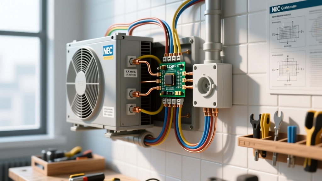
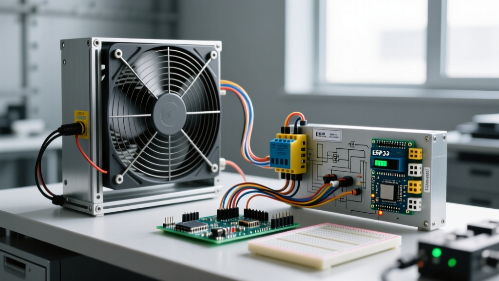
When we discuss wiring electric fans with relay systems in a commercial context, we are actually wiring a low-amperage control relay (or smart building automation controller) to energize the coil of a heavy-duty magnetic contactor, which in turn switches the high-amperage fan motor.
2026 Component Selection Matrix for Commercial Fans
Selecting the correct contactor and control transformer requires matching the motor's horsepower (HP), voltage, and FLA. Below is a selection matrix based on current 2026 commercial pricing and standard HVAC configurations.
| Application Scenario | Motor Specs (HP / Voltage / FLA) | Recommended Contactor Type & Model | Control Transformer | Est. Material Cost (2026) |
|---|---|---|---|---|
| Single-Phase Rooftop Exhaust | 2 HP / 240V / 12A FLA | Definite Purpose 40A (e.g., Eaton C25CNF240B) | 40VA 24VAC | $65 - $85 |
| Three-Phase Warehouse Circulator | 5 HP / 208V / 17.5A FLA | IEC 3-Pole 25A (e.g., Schneider TeSys LC1D25) | 75VA 24VAC | $140 - $180 |
| Server Room Precision Cooling | 3 HP / 480V / 4.8A FLA | NEMA Size 1 (e.g., Eaton XTCE009B) | 50VA 24VAC | $210 - $260 |
Note: Always verify the specific motor nameplate data. Never size a contactor based solely on horsepower; FLA and LRA dictate the true thermal and magnetic requirements.
Step-by-Step: Wiring the Load and Control Circuits
Proper execution requires dividing the installation into two distinct circuits: the line-voltage load circuit and the low-voltage control circuit.
Phase 1: The Line-Voltage Load Circuit
- Install the Disconnect: Per NEC Article 430, a fused disconnect switch or motor circuit switch must be installed within sight of the fan motor. For a 240V single-phase fan, use a 60A, 240V NEMA 3R (outdoor) or NEMA 1 (indoor) disconnect.
- Wire the Contactor Line Side: Run appropriately sized THHN/THWN conductors (e.g., 10 AWG for up to 30A) from the load side of the disconnect to the L1 and L2 terminals on the magnetic contactor.
- Wire the Contactor Load Side: Run conductors from the T1 and T2 terminals on the contactor to the motor's junction box. Critical Edge Case: If the run exceeds 50 feet, calculate voltage drop. A 3% voltage drop on a motor circuit increases the FLA, causing premature thermal overload trips.
- Grounding: Bond the equipment grounding conductor (EGC) directly to the motor chassis and the contactor backplate. Do not route the EGC through the contactor's switching poles.
Phase 2: The Low-Voltage Control Circuit
- Mount the Transformer: Install a 40VA or 50VA, 24VAC control transformer (e.g., Functional Devices TR40VA). Wire the primary side (120V or 208V/240V) with an inline 3-amp fuse on the hot leg to protect the low-voltage wiring.
- Wire the Thermostat / Automation Relay: Connect the 24VAC 'Hot' (R) from the transformer to your commercial thermostat, building automation system (BAS) relay, or occupancy sensor.
- Complete the Coil Circuit: Run the switched 24VAC 'Call' wire (W or Y) from the controller to the A1 terminal on the contactor coil. Connect the transformer's 24VAC 'Common' (C) to the A2 terminal on the coil.
Protecting Smart Controllers from Inductive Kickback
One of the most frequent failure modes in modern commercial retrofits is the destruction of smart thermostats (like Ecobee or advanced Honeywell commercial BAS modules) when wiring electric fans with relay coils. When the contactor coil de-energizes, the collapsing magnetic field generates a massive reverse voltage spike (inductive kickback) that travels back down the 24V control wire, frying the solid-state triac inside the smart controller.
Expert Mitigation Strategy: Always install an RC snubber network (a resistor and capacitor in series) or a bidirectional TVS diode across the A1 and A2 coil terminals of the contactor. A $4 component like the Schneider Electric LAD4VU snubber will absorb the inductive spike, saving your $300 commercial smart thermostat from instant destruction.
Common Failure Modes and Troubleshooting
Even with proper installation, commercial fan circuits face harsh environments. Here is how to diagnose the three most common field failures:
- Contact Welding: If the fan refuses to turn off even when the thermostat drops the 24V signal, the contactor's main poles have likely welded together due to LRA inrush arcing. Fix: Replace the contactor with a higher NEMA size or ensure the overload relay is tripping fast enough to protect the contacts.
- Contactors Chattering (Humming Loudly): This occurs when the shading coil inside the contactor's magnetic armature is compromised, or when there is severe voltage drop on the 24V control wire run. Fix: Measure the voltage directly at A1/A2 while energized. If it reads below 20VAC on a 24V system, upgrade the control wire from 18 AWG to 16 AWG or install a booster relay closer to the contactor.
- Nuisance Overload Trips: If the bimetallic overload relay trips randomly on hot days, the ambient temperature inside the electrical panel may be exceeding the overload's compensation rating. Fix: Install a panel ventilation louver or relocate the overload relay outside the high-heat enclosure.
NEC Code Compliance for Motor Circuits
Commercial electricians must adhere strictly to NFPA 70 (National Electrical Code), specifically Article 430, which governs motors and motor controllers. Key compliance points for 2026 inspections include:
- Overload Protection (NEC 430.32): You must install a dedicated motor overload relay (either integrated into the contactor assembly as a 'motor starter' or as a separate block) sized between 115% and 125% of the motor's nameplate FLA. The branch circuit breaker protects the wire; the overload relay protects the motor.
- Controller HP Rating (NEC 430.83): The contactor must have a horsepower rating equal to or greater than the fan motor's horsepower rating at the applied voltage. Using a lighting contactor rated for 20 Amps on a 3 HP motor is a direct code violation, as lighting contactors lack the HP-rated arc extinction capabilities required for inductive motor loads.
- Disconnecting Means (NEC 430.102): A means to disconnect the controller must be provided. For commercial rooftop units, this often requires a lockable disconnect within sight of the motor and the controller enclosure.
For comprehensive safety standards regarding electrical wiring methods and motor control enclosures in commercial facilities, always cross-reference OSHA's electrical safety guidelines to ensure workplace compliance during installation and maintenance.
Final Thoughts on Commercial Fan Automation
Wiring commercial ventilation requires a deep respect for inductive physics. By correctly pairing a low-voltage control relay with a properly sized magnetic contactor, integrating RC snubbers, and adhering to NEC Article 430 overload requirements, you ensure a system that operates reliably for decades. For further reading on selecting the correct IEC and NEMA motor starters for complex 3-phase exhaust arrays, consult the Schneider Electric industrial control documentation or the specific manufacturer's motor starting guides before finalizing your panel layouts.