
The Critical Nature of Trailer Brake Circuits
When you are towing a 7,000-pound travel trailer or a dual-axle equipment hauler, the electrical circuit controlling your brakes is the single most important safety system on your rig. A failure in trailer electric brakes wiring does not just result in a blown fuse; it results in a catastrophic loss of stopping power. According to the Federal Motor Carrier Safety Administration (FMCSA), all brakes on a commercial or heavy-duty trailer combination must be operative and capable of stopping the vehicle within strict distance parameters. While DIY enthusiasts often focus on the mechanical installation of brake assemblies, the electrical architecture is where the most dangerous, silent failures occur.
In 2026, with modern proportional brake controllers like the Tekonsha Prodigy P3 (Model 90195) and the Redarc Tow-Pro Elite V2 pushing precise pulse-width modulation (PWM) signals to the axles, your wiring harness must be built to handle dynamic electrical loads without voltage drop. This guide details the exact specifications, safety protocols, and failure-prevention strategies required for professional-grade trailer brake wiring.
Wire Gauge Realities: The 10 AWG vs. 12 AWG Debate
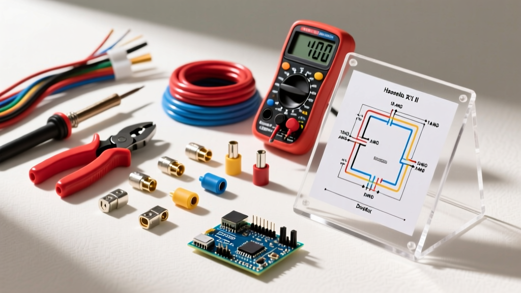
The most common point of failure in aftermarket trailer wiring is the use of undersized wire for the brake output circuit. Many pre-fabricated, off-the-shelf 7-way harnesses utilize 12 AWG wire for all circuits to cut manufacturing costs. While 12 AWG is sufficient for tail lights and running lights, it is dangerously inadequate for electric brakes.
Calculating Voltage Drop on Dual-Axle Trailers
A standard 12-inch electric brake magnet draws approximately 3.5 to 4 amps at 12 volts. On a dual-axle trailer (four brakes), the total draw can spike to 15 amps during a hard, emergency braking event. If you are using 25 feet of 12 AWG copper wire, the resistance will cause a voltage drop of roughly 1.5 volts. This means your brake magnets are only receiving 10.5 volts, reducing your braking torque by up to 20%.
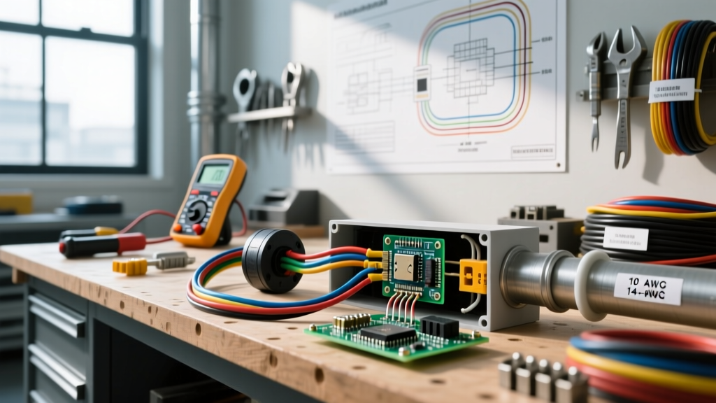
- The Standard: Always use 10 AWG stranded copper wire (industry-standard blue jacket) for the brake output feed from the 7-way connector to the axle junction box.
- The Upgrade: For triple-axle trailers (six brakes drawing up to 22 amps), step up to 8 AWG wire for the main trunk line to eliminate voltage drop entirely.
- Wire Type: Use SAE J1128 compliant stranded copper wire with cross-linked polyethylene (XLPE) insulation to resist undercarriage heat, road salt, and UV degradation.
The Grounding Protocol: Eliminating the 'White Wire' Failure
The RV Industry Association (RVIA) consistently identifies poor grounding as the number one cause of erratic trailer brake behavior, blown fuses, and back-feeding through the tail light circuit. The white ground wire in your 7-way harness is not a suggestion; it is the return path for the entire 15+ amp brake circuit.
Expert Rule of Thumb: Never rely on the trailer hitch ball and coupler as a ground path. The articulation of the hitch, combined with grease, rust, and paint, creates massive electrical resistance. The ground must be hardwired.
Proper Grounding Execution:
- Run a dedicated 10 AWG white ground wire from the 7-way plug directly to the trailer frame.
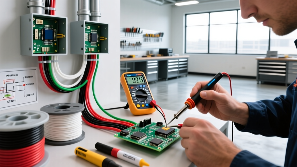
- Strip the wire, crimp on a heavy-duty, heat-shrink ring terminal (use a ratcheting crimper, not pliers).
- Locate a thick, structural section of the steel frame. Sand away all paint, powder coating, and rust down to bare, shiny metal.
- Secure the ring terminal using a Grade 8 bolt, a flat washer, and a star washer to bite into the metal.
- Coat the entire terminal connection with marine-grade dielectric grease to prevent galvanic corrosion.
7-Way RV Blade Pinout and Safety Standards
Standardization is critical for safety. The 7-way RV blade connector follows strict SAE and RVIA pinout guidelines. Miswiring the 12V auxiliary pin with the brake output pin will instantly destroy your brake controller and potentially ignite the trailer's breakaway battery.
| Pin Position (Clockwise) | Function | Wire Color | Min. Gauge | Safety Notes |
|---|---|---|---|---|
| 1 (Top Center) | 12V Auxiliary Power | Black | 10 AWG | Must be on a 40A auto-reset breaker at the tow vehicle. |
| 2 (Top Right) | Electric Brakes Output | Blue | 10 AWG | PWM signal from controller. Do not splice with 12V aux. |
| 3 (Bottom Right) | Ground | White | 10 AWG | Must bond directly to bare chassis metal. |
| 4 (Bottom Left) | Left Turn / Stop | Yellow | 12 AWG | Use heat-shrink butt splices only. |
| 5 (Top Left) | Right Turn / Stop | Green | 12 AWG | Verify with a circuit tester before plugging in. |
| 6 (Center) | Tail / Running Lights | Brown | 12 AWG | Most prone to voltage drop on long trailers; consider 10 AWG. |
| 7 (Center Left) | Backup Lights / Aux | Purple | 14 AWG | Often used for reverse lockout solenoids on surge brakes. |
Breakaway Switch Wiring: Avoiding the 'Parallel Trap'
The breakaway system is your last line of defense if the trailer physically separates from the tow vehicle. It consists of a pin-pull switch and a dedicated 12V battery (typically a 5Ah Sealed Lead Acid like the Mighty Max ML5-12, or a modern LiFePO4 upgrade like the RELiON RB12V5).
The Fatal Mistake: Many DIYers wire the breakaway battery directly in parallel with the main 12V auxiliary feed from the tow vehicle, without an isolation solenoid. When the tow vehicle is connected, the truck's alternator (outputting 14.4V) constantly force-charges the small 5Ah breakaway battery, leading to thermal runaway, battery swelling, and eventual failure. When a real breakaway event occurs, the battery is dead.
The Correct Breakaway Wiring Architecture
- Isolation: Use a breakaway kit with a built-in trickle-charge isolation module, or wire a dedicated 10-amp diode between the 12V auxiliary feed and the breakaway battery to prevent overcharging.
- The Switch Path: The breakaway switch must be wired in parallel with the blue brake output wire, but upstream of the brake magnets. When the pin is pulled, the switch connects the breakaway battery directly to the blue wire, sending 12V to the brakes independently of the tow vehicle.
- Battery Sizing: FMCSA and RVIA standards dictate the breakaway battery must have enough capacity to hold the brakes fully locked for a minimum of 15 minutes. A standard 5Ah SLA is sufficient for dual axles; upgrade to 7Ah or higher for triple-axle setups.
Proportional Brake Controller Integration
Modern proportional controllers like the Curt Spectrum (Model 51170, approx. $160) or the Tekonsha Prodigy P3 (approx. $175) rely on internal accelerometers to match the tow vehicle's deceleration. To function safely, they require three distinct wiring inputs:
- Black Wire (12V Power): Must be routed directly to the vehicle's battery through a 30A or 40A auto-reset circuit breaker. Never tap into the vehicle's ignition switch or fuse box for power; the inrush current can melt standard automotive fuse taps.
- Red Wire (Stoplight Signal): This must be connected to the cold side of the vehicle's brake light switch. If wired to the hot side, the controller will think you are constantly braking, leading to overheated magnets and premature failure.
- Blue Wire (Brake Output): The PWM output routed to the 7-way connector. Ensure this wire does not run parallel to the vehicle's CAN-bus data lines, as the high-frequency PWM signal can induce electromagnetic interference (EMI) in modern truck computers.
Diagnostic Matrix: Failure Modes and Corrections
When troubleshooting trailer electric brakes wiring, use a digital multimeter (DMM) and a dedicated trailer brake tester (like the Tow-Rite or Tekonsha Tester) rather than relying solely on the truck's dashboard display.
| Symptom | Root Cause / Failure Mode | Corrective Action |
|---|---|---|
| Brakes pulse or grab erratically | Corroded ground connection or loose ring terminal on the white wire. | Clean frame contact point to bare metal; replace terminal with heat-shrink ratcheted crimp. |
| Controller displays 'S.H.' or 'O.L.' | Short circuit in the blue wire (chafing against axle) or blown magnet coil. | Inspect blue wire routing near U-bolts; test individual magnets (should read 3.0 - 4.0 ohms). |
| Brakes lock up when headlights are on | Back-feeding due to a shared ground or melted 7-way connector pins. | Separate the ground circuits; inspect 7-way plug for melted plastic or pushed-back pins. |
| Breakaway battery is swollen/hot | Alternator overcharging the SLA battery due to missing isolation diode. | Install a breakaway battery isolation solenoid or replace with a LiFePO4 battery with a built-in BMS. |
Final Safety Inspections
Before hitting the road, perform a static drag test. Jack up the trailer so the wheels are off the ground. Spin the wheels by hand and have an assistant manually slide the brake controller override lever to 100%. The wheels should lock immediately and stop spinning. If a wheel continues to spin, you have a localized wiring fault or a failed magnet at that specific hub. Proper trailer electric brakes wiring is not just about making the lights turn on; it is about engineering a fail-safe electrical architecture that protects your life and the lives of others on the highway.