
Decoding Electrical Wiring Colours Blue and Brown
When working on modern electrical installations, encountering non-standard cable insulation can trigger immediate safety alarms. For North American electricians and DIYers, understanding electrical wiring colours blue and brown is not just a matter of code compliance—it is a critical life-safety skill. While the US and Canada rely on the National Electrical Code (NEC) which mandates black/red for hot, white for neutral, and bare/green for ground, the rest of the world operates on a completely different color spectrum.
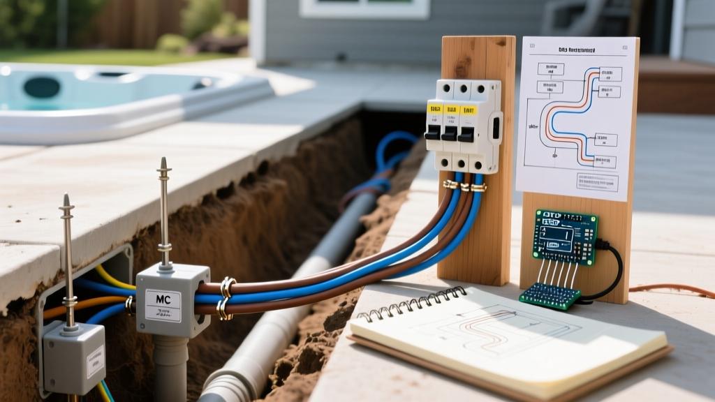
The harmonization of European and international wiring colors under the IEC 60446 standard (adopted in the UK via BS 7671) designates Brown as Line (Active/Hot) and Blue as Neutral. If a technician assumes a brown wire is a neutral (confusing it with the US black/white paradigm where dark colors are hot and light colors are neutral, though brown is dark), they risk catastrophic short circuits, equipment destruction, or lethal electrocution. This guide details the safety protocols, identification matrices, and termination best practices for handling blue and brown wiring in 2026.
Global Color Code Comparison Matrix
Before touching any conductor, you must identify the origin of the equipment or the governing standard of the installation. The table below contrasts the IEC standard with other major global frameworks.
| Function | IEC / UK / EU (BS 7671) | US / Canada (NEC CEC) | Australia / NZ (AS/NZS 3000) |
|---|---|---|---|
| Line / Active (Hot) | Brown (L1), Black (L2), Grey (L3) | Black (L1), Red (L2), Blue (L3) | Red (L1), White (L2), Blue (L3) |
| Neutral | Blue | White or Grey | Black |
| Protective Earth | Green/Yellow Stripe | Green, Yellow, or Bare | Green/Yellow Stripe |
Source reference: Color codes verified against the UK Health and Safety Executive (HSE) and international IEC guidelines.
Where North American Electricians Encounter Blue and Brown
You might wonder why IEC color codes matter if you are wiring a home in Ohio or Ontario. In today's globalized supply chain, blue and brown wires frequently appear in North American residential and commercial environments in three specific scenarios:
1. Imported Premium Appliances
High-end European appliances—such as Miele dishwashers, Bosch ovens, and Smeg refrigeration units—often ship with hardwired pigtails featuring brown, blue, and green/yellow conductors. While the internal components may be adapted for 60Hz North American power, the factory-installed external whips often retain IEC coloring. Connecting a blue neutral to a US black hot busbar will instantly destroy the appliance's control board and trip the main breaker.
2. Industrial Control Panels and VFDs
Under NFPA 79 and IEC 61439, industrial control panels built by multinational OEMs (like Siemens or ABB) frequently use blue for DC or AC neutral control circuits, and brown for single-phase AC line voltage. When troubleshooting a Variable Frequency Drive (VFD) or PLC enclosure, assuming US NEC colors inside an IEC-wired cabinet is a leading cause of arc flash incidents.
3. Marine, RV, and Off-Grid Solar Systems
Many imported marine inverters and off-grid solar charge controllers utilize IEC color coding for their AC input/output terminals. Victron Energy equipment, for example, clearly labels terminals but relies on standard IEC brown/blue cabling in its pre-assembled AC bypass kits.
Step-by-Step Safety Verification Protocol
The golden rule of electrical safety is to never trust insulation color. A previous installer may have used whatever scrap wire was available, or an imported cordset may have been mislabeled. Follow this strict verification protocol:
- Isolate and LOTO: Turn off the main breaker supplying the circuit. Apply a Lockout/Tagout (LOTO) device to the panel to prevent accidental re-energization.
- Non-Contact Voltage Test (NCVT): Use a dual-range tester like the Klein Tools NCVT-41 (rated for 12V to 1000V AC). Test the brown and blue wires independently. The brown (Line) should trigger the high-voltage alarm; the blue (Neutral) should not, provided the circuit is de-energized at the source. If testing a live cordset before connection, the brown wire will register voltage.
- Multimeter Verification: Set a CAT III 600V True-RMS multimeter (such as the Fluke 117) to AC Voltage. Measure between Brown and Green/Yellow (should read ~120V or ~230V depending on the system). Measure between Blue and Green/Yellow (should read 0V or <2V phantom voltage). Measure between Brown and Blue (should read full line-to-line voltage).
- Continuity Check: With power OFF, use the multimeter's continuity setting to verify the Blue wire connects directly to the neutral busbar or appliance neutral terminal, and the Green/Yellow connects to the grounding bus.
CRITICAL SAFETY WARNING: According to the National Fire Protection Association (NFPA), all conductors must be identified and verified before termination. Relying solely on visual color identification without live/dead testing violates core safety principles and risks fatal shock hazards.
Termination Hardware: Pigtailing IEC to NEC
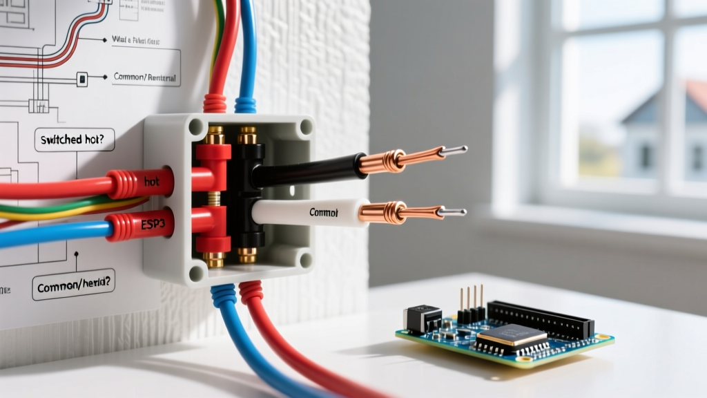
When you must connect an appliance's brown/blue/green-yellow pigtail to a standard US junction box containing black/white/bare wires, proper termination hardware is essential. Traditional twist-on wire nuts can struggle with the differing strand counts and metric gauge sizes (e.g., 1.5mm² or 2.5mm²) typical of IEC cords.
The WAGO 221 Series Advantage
For transitioning between metric IEC wiring and AWG NEC wiring, lever-nut connectors are the industry standard. The WAGO 221-412 (2-conductor) or 221-413 (3-conductor) lever nuts are rated for 32A and 600V, accommodating wire sizes from 24 to 12 AWG (0.2 to 4mm²).
- Stripping Length: Use a precision stripper (like the Knipex MultiStrip 10) to strip exactly 11mm of insulation from both the brown/blue metric wires and the black/white AWG wires.
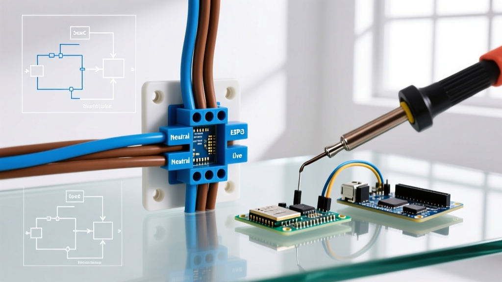
- Termination Sequence: Insert the Brown wire alongside the Black (Hot) wire into the WAGO 221-412 and clamp the levers down. Insert the Blue wire alongside the White (Neutral) wire into a second WAGO connector.
- Labeling: Wrap a piece of Brady BPMC-175 wire marker tape around the junction, noting "IEC to NEC Pigtail - Brown=Hot, Blue=Neutral" to protect future technicians.
Common Failure Modes and Edge Cases
Even when colors are correctly identified, integrating blue and brown IEC equipment into North American split-phase or single-phase systems presents unique edge cases.
GFCI Nuisance Tripping on Imported 240V Equipment
Many European appliances (like Bosch heat pump dryers) are designed for 230V single-phase, 50Hz power where the Blue neutral is bonded to the chassis earth at the main service entrance. In North America, 240V is achieved via split-phase (two 120V hot legs, no neutral). If an appliance's internal EMI filter routes high-frequency noise to the Blue wire, and that Blue wire is improperly bonded to a US Ground, it will cause immediate nuisance tripping on AFCI/GFCI breakers. Solution: Always verify the appliance's internal wiring diagram. Some OEMs require the removal of a specific neutral-to-ground bonding jumper inside the appliance's terminal block before connecting it to a US 240V receptacle.
Induced Voltages in Long Blue Neutral Runs
When running multi-conductor IEC control cables alongside high-current VFD lines, the Blue neutral wire can pick up significant induced electromagnetic interference (EMI). This phantom voltage can trick high-impedance digital multimeters into reading 40V-60V on a dead neutral circuit. To safely verify a dead Blue wire, use a low-impedance (LoZ) tester or the LoZ mode on a Fluke 117 to bleed off phantom capacitive coupling before touching the conductor. For deeper insights into multimeter safety categories and LoZ testing, refer to the Fluke Corporation Safety Guidelines.
Final Safety Directives for 2026
As global supply chains continue to blend international equipment into local markets, the rigid adherence to localized color codes is no longer sufficient. Mastering the identification, testing, and termination of electrical wiring colours blue and brown ensures that your installations remain safe, code-compliant, and resilient against the hazards of cross-standard confusion. Always test before you touch, leverage modern lever-nut terminations for mixed-gauge connections, and document every transition point for the safety of the next technician.