
The Critical Distinction: Switchboards vs. Panelboards
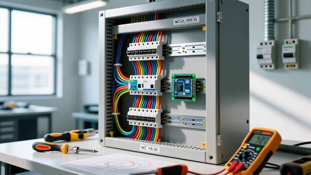
Before initiating any inspection protocol, electrical professionals must distinguish between a switchboard and a panelboard. While often used interchangeably in casual conversation, the National Electrical Code (NEC) and Underwriters Laboratories (UL) treat them as distinct entities with different compliance frameworks. Switchboards are typically freestanding, floor-mounted assemblies built to UL 891 and NEMA PB-2 standards, designed for higher fault currents and accessible from the front, rear, or sides. Panelboards, governed by UL 408 and NEMA PB-1, are surface or flush-mounted and accessible only from the front.
For electrical inspectors and facility managers in 2026, applying the correct code articles—primarily NEC Article 408 for both, alongside specific installation rules in Articles 110, 250, and 312—is the foundation of a compliant electrical switchboard wiring assessment. Failure to recognize the specific mechanical and thermal tolerances of switchboards frequently leads to catastrophic arc flash incidents or chronic harmonic heating.
Working Space and Wire Bending Clearances
One of the most frequently cited violations during commercial and industrial inspections involves insufficient working space and wire bending clearances. According to OSHA 1910.303 and NEC 110.26, the minimum depth of the working space in front of a switchboard must be 3 feet, 3.5 feet, or 4 feet, depending on the nominal voltage to ground and the presence of exposed live parts on the opposite side of the workspace.
Inspector Note: The 2023 NEC (and subsequent 2026 adoptions) strictly enforces the 'dedicated equipment space' rule. No foreign systems (HVAC ducts, plumbing, fire suppression) may be installed in the zone extending from the floor to a height of 6 feet above the switchboard or to the structural ceiling, whichever is lower.
Beyond the frontal working space, internal wire bending space is heavily regulated under NEC 312.6. When wiring a switchboard, conductors must not be deflected at sharp angles. For a 3/0 AWG conductor, the minimum wire bending space at the terminal is 4 inches. If the installer uses a 90-degree connector or pulls conductors through a knockout that forces a tight bend radius, the insulation jacket is subjected to severe mechanical stress, leading to micro-tears that eventually cause phase-to-ground faults.
The Torque Mandate: NEC 110.14(D) Compliance
The era of the 'calibrated elbow' is over. Modern electrical switchboard wiring requires strict adherence to NEC 110.14(D), which mandates that all mechanically connected terminations must be torqued to the manufacturer's specified values using calibrated instruments. This is not a recommendation; it is an enforceable code requirement.
Why Torque Matters in 2026
- Cold Flow: Aluminum busbars and conductors exhibit 'cold flow' (creep), meaning they deform under continuous pressure. An over-torqued connection will slowly loosen over 12 to 18 months as the aluminum yields, increasing contact resistance.
- Thermal Expansion: Under-torqued connections allow microscopic movement during thermal cycling (load fluctuations), causing arcing, oxidation, and eventual thermal runaway.
- Harmonic Loads: Modern VFDs and LED drivers generate triplen harmonics that heavily load the neutral busbar. Loose neutral terminations will overheat rapidly under these conditions.
Actionable Tooling: Inspectors should look for torque seals (lacquer dots) applied by the installing electrician. For verification, use a calibrated torque screwdriver like the CDI Torque 401SM (for inch-pound terminations up to 100 in-lbs) or a digital torque adapter like the ACDelco ARM601-4 for larger lug bolts. A standard 14 AWG copper wire typically requires 12 to 15 in-lbs, but the manufacturer's chart on the switchboard interior door always supersedes general tables.
Common Switchboard Inspection Failures & Corrective Actions
Based on field data and NFPA 70 (NEC) enforcement trends, the following table outlines the most critical wiring failures encountered during switchboard inspections.
| Failure Mode | NEC Violation | Root Cause & Risk | Corrective Action & Est. Cost |
|---|---|---|---|
| Double-Tapped Neutrals | 408.41 | Two neutral wires under one screw. Risk of back-feeding and shock during maintenance. | Add a pigtail or install an auxiliary neutral bar. ($150 - $300) |
| Missing Main Bonding Jumper | 250.92(B) | Neutral and ground isolated at the service entrance. Risk of failure to clear ground faults. | Install correctly sized copper bonding jumper per Table 250.102(C)(1). ($200 - $500) |
| Phase Identification Missing | 210.4(D) / 408.3(E) | Multi-wire branch circuits or switchboard phases lack color-coding or labeling. | Apply permanent phase identification tape and update panel directory. ($75 - $150) |
| Unused Openings Unsealed | 110.12 / 408.14 | Missing knockout seals. Risk of debris/rodent ingress causing short circuits. | Install UL-listed metal hub seals or knockout washers. ($50 - $100) |
| Conductors Resting on Sharp Edges | 300.4(B) | Wires dragged across un-bushed metal knockouts. Insulation degradation over time. | Reroute wires, install insulating bushings, and apply abrasion guards. ($250 - $400) |
Infrared Thermography & NETA Inspection Protocols
Visual inspection of electrical switchboard wiring is insufficient for detecting high-resistance connections. In 2026, comprehensive compliance requires Infrared (IR) Thermography under loaded conditions. Following the NETA ATS (Acceptance Testing Specifications), inspectors should utilize a high-resolution thermal camera (such as the FLIR E8-XT or Fluke TiS60+) to scan busbar joints, breaker terminations, and neutral lugs.
Delta T (ΔT) Thresholds for Action
- ΔT of 1°C to 3°C: Indicates a possible deficiency. Monitor during the next scheduled outage.
- ΔT of 4°C to 15°C: Indicates a probable deficiency. Requires tightening or termination replacement within 30 days.
- ΔT > 15°C: Major discrepancy. Immediate load reduction and emergency repair required to prevent fire or arc flash.
Pro Tip: Always measure the baseline temperature of an identical, adjacent phase to calculate the Delta T. Do not rely solely on the absolute temperature reading, as ambient room temperature and solar loading can skew raw data.
Grounding, Bonding, and Neutral Isolation
A frequent point of confusion during switchboard wiring inspections is the handling of the neutral and ground buses. In a service entrance switchboard (the main disconnecting means), the neutral busbar must be bonded to the ground busbar and the enclosure via the main bonding jumper. However, in all downstream separately derived systems or sub-feed switchboards, the neutral busbar must be completely isolated from the equipment grounding busbar.
Inspectors must physically verify this isolation. Look for the green plastic insulators isolating the neutral bar from the metal enclosure, and ensure that no rogue bonding screws or straps have been mistakenly installed by well-meaning but misinformed technicians. Furthermore, per the Electrical Safety Foundation International (ESFI) guidelines, all equipment grounding conductors must be routed separately from the neutral conductors to prevent parallel neutral currents from energizing the switchboard enclosure.
Frequently Asked Questions (FAQ)
Can I use aluminum wiring for switchboard feeders?
Yes, AA-8000 series aluminum alloy conductors are code-compliant and widely used for large switchboard feeders due to cost and weight advantages. However, you must use dual-rated (AL/CU) lugs, apply an oxide inhibitor compound (like Noalox), and strictly adhere to aluminum-specific torque values, which are often lower than copper equivalents to prevent thread stripping.
Are AFCI and GFCI breakers required in commercial switchboards?
GFCI protection is required for specific receptacle outlets (e.g., 15A/20A, 125V) per NEC 210.8, and AFCI is generally mandated for residential dwelling units. Commercial switchboards feeding heavy machinery or continuous industrial loads typically do not require AFCI protection, as nuisance tripping can create greater safety hazards in industrial environments.
How often should switchboard wiring be re-torqued?
The NEC does not specify a mandatory re-torquing schedule. However, NETA Maintenance Testing Specifications (MTS) recommend thermographic inspections annually. If thermal anomalies are detected, or if the switchboard is subjected to heavy vibration or frequent fault current events, mechanical re-torquing of bus joints and cable terminations should be performed during scheduled shutdowns.