
Electric Trailer Brake Controller Wiring: The 2026 Inspection & Compliance Standard
When hauling heavy loads, the integrity of your electric trailer brake controller wiring is not just a matter of convenience; it is a critical safety and legal requirement. Improperly routed, undersized, or degraded wiring can lead to catastrophic brake failure, electrical fires, or DOT compliance violations during commercial inspections. As of 2026, both recreational and commercial towing standards have tightened, requiring stricter adherence to voltage drop limits, circuit protection placement, and wire insulation ratings.
This comprehensive guide dives deep into the inspection and compliance protocols for electric trailer brake controller wiring. Whether you are outfitting a heavy-duty commercial fleet or upgrading a personal tow rig, understanding the exact specifications for wire gauges, circuit breakers, and 7-way pinouts will ensure your system passes rigorous safety inspections and performs flawlessly under load.
Regulatory Framework & Code Requirements
Trailer brake wiring intersects with several regulatory bodies. For commercial applications, the Federal Motor Carrier Safety Administration (FMCSA) mandates strict brake functionality. According to FMCSA Title 49 § 393.42, every commercial motor vehicle must have brakes adequate to control the movement and to stop and hold the vehicle under all conditions of loading. While this primarily targets the braking hardware, the electrical delivery system must reliably support these hardware requirements without voltage degradation.
For recreational vehicles and general automotive applications, wiring must align with principles outlined in the National Fire Protection Association (NFPA 70) National Electrical Code (NEC), specifically regarding overcurrent protection and chassis grounding in mobile environments. Furthermore, the RV Industry Association (RVIA) enforces strict low-voltage DC wiring standards that dictate wire type, routing, and circuit breaker placement.
Circuit Breaker Placement & Sizing
A common failure point during state DOT or RVIA inspections is the placement and rating of the main circuit breaker feeding the brake controller.
- Placement Rule: The main overcurrent protection device (circuit breaker or maxi-fuse) must be installed within 18 inches of the positive battery terminal. This protects the entire length of the primary power cable from short-circuiting against the chassis.
- Sizing Specifications: Most modern proportional brake controllers (drawing up to 6-8 axles) require a 40-amp circuit breaker. Use a Bussmann CB185-40 (Type 2 manual-reset) for commercial rigs to prevent auto-resetting during a hard short, or a CB181-40 (Type 1 auto-reset) for standard RV applications.
Wire Selection: Gauge, Insulation, and Routing
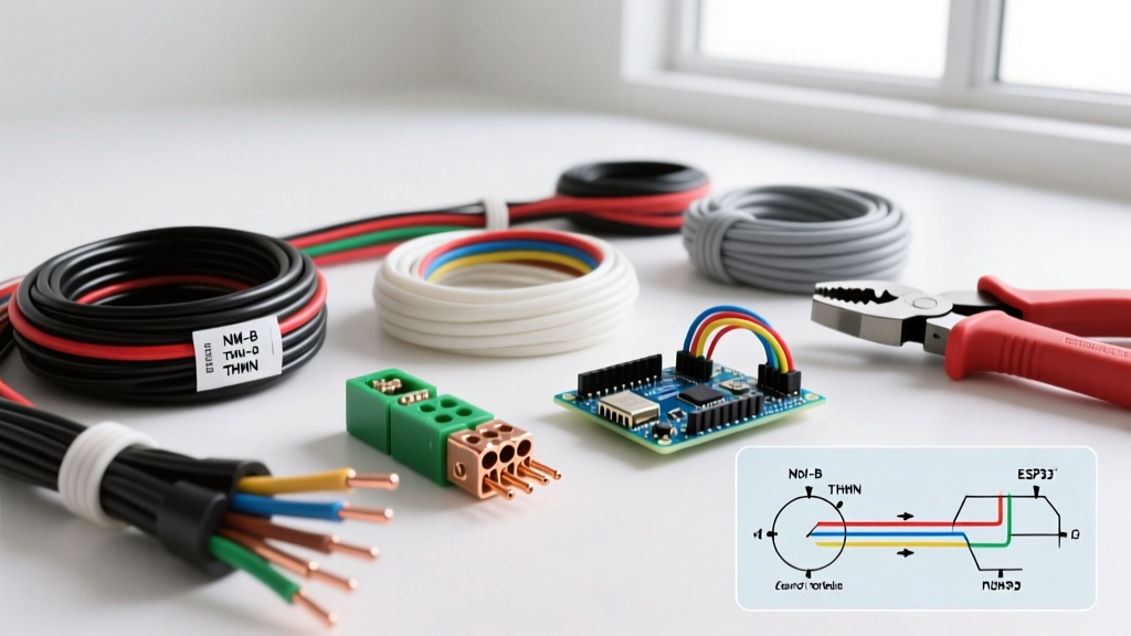
Using standard THHN household wire or cheap automotive primary wire for trailer brake circuits is an immediate red flag during compliance inspections. Mobile environments subject wiring to extreme vibration, thermal cycling, and chemical exposure (road salt, oil, transmission fluid).
Approved Wire Types for Brake Controllers
| Wire Type | Temp Rating | Insulation Material | Best Application |
|---|---|---|---|
| SGT | 105°C | PVC | Standard RV, light-duty towing, interior cab runs. |
| GXL | 125°C | Cross-linked Polyethylene (XLPE) | Engine bay routing, heavy-duty commercial, high-heat zones. |
| TXL | 125°C | XLPE (Thin-wall) | Tight harness wraps, weight-sensitive aerospace/RV builds. |
Expert Specification: For the main power feed from the battery to the controller, and the output feed to the 7-way connector, you must use a minimum of 10 AWG wire. While some manufacturers suggest 12 AWG for short runs, 10 AWG is the compliance standard for runs exceeding 12 feet to mitigate voltage drop. Always use stranded copper; solid core wire will fracture under vehicular vibration.
The 7-Way RV Blade Pinout & Compliance Matrix
The 7-way RV blade connector is the industry standard for electric trailer brakes. During an inspection, technicians will verify that the pinout matches the SAE J2807 and RVIA standard color codes. Deviating from these colors can cause severe diagnostic issues and fail compliance audits.
| Pin Position | Function | Standard Wire Color | Min. Gauge | Inspection Note |
|---|---|---|---|---|
| 1 (Top Left) | Left Turn / Stop | Yellow | 12 AWG | Check for LED-compatible flasher relays. |
| 2 (Bottom Left) | Reverse Lights | Purple | 14 AWG | Verify isolation from brake circuit. |
| 3 (Center) | Ground (White) | White | 10 AWG | Critical: Must be ring-terminated to bare chassis metal. |
| 4 (Top Right) | Right Turn / Stop | Green | 12 AWG | Test for voltage drop under load. |
| 5 (Bottom Right) | Electric Brakes | Blue | 10 AWG | Direct feed from controller; no splices allowed. |
| 6 (Center Left) | Tail / Marker Lights | Brown | 12 AWG | Verify 30A maxi-fuse protection at source. |
| 7 (Center Right) | 12V Auxiliary Power | Black or Red | 10 AWG | Must have 40A breaker within 18" of battery. |
2026 Market: Top Compliant Brake Controllers
When installing or replacing a controller, selecting a unit that meets modern electromagnetic interference (EMI) and CAN-bus integration standards is vital. Here are the top compliant models for 2026:
1. Tekonsha Prodigy P3 (Model 90195)
- Price Range: $160 - $185
- Compliance Edge: Features built-in diagnostic checks for shorts and power loss. Its proportional inertia sensor meets strict SAE J2807 testing parameters for smooth deceleration curves.
- Wiring Note: Requires a dedicated 12V+ (Black), Ground (White), Brake Input (Red), and Trailer Output (Blue).
2. REDARC Tow-Pro Elite (Model EBRH-ACCV2)
- Price Range: $210 - $235
- Compliance Edge: Active calibration and dual-mode (proportional/user-controlled) switching. Highly resistant to voltage spikes common in modern alternator systems.
- Wiring Note: Uses a color-coded fly-lead harness; requires solder-seal connectors (not standard crimp caps) for moisture resistance.
3. CURT Spectrum (Model 51175)
- Price Range: $220 - $250
- Compliance Edge: Tri-core inertial sensor and plug-and-play OEM integration modules that prevent voiding factory CAN-bus warranties.
The DOT & RVIA Inspection Checklist
If you are preparing a vehicle for commercial DOT inspection or RV dealership certification, run through this specific electrical checklist. Inspectors will look for these exact failure modes:
- Chassis Ground Integrity: The white ground wire must not be grounded to painted metal or rust. Inspectors will scratch the grounding point to verify bare metal contact. A star washer must be used under the ring terminal to bite into the chassis.
- Wire Loom & Chafing Protection: Any wire passing through a metal bulkhead or frame rail must be protected by a rubber grommet. Split loom tubing must be used for all undercarriage runs. Exposed zip-ties with sharp edges cutting into wire insulation is an automatic fail.
- Splice Prohibitions: The blue electric brake wire running from the controller to the 7-way connector must be a single, continuous run. Twist-on wire nuts, T-taps, and electrical tape splices are strictly prohibited in mobile brake circuits. Only solder-sealed heat shrink (e.g., Ancor Marine Grade) is acceptable if a repair is mandatory.
- Connector Corrosion (Green Rot): Inspect the 7-way plug pins for copper oxidation. Dielectric grease (e.g., Permatex 22058) must be applied to the pins to prevent moisture ingress, which increases resistance and lowers brake actuation voltage.
Inspector's Note: "Over 40% of trailer brake electrical failures we see on the road are not due to the brake controller itself, but due to a degraded ground wire or a corroded 7-way plug causing a voltage drop below the 9V minimum required to actuate the trailer's electromagnets." — Commercial Vehicle Safety Alliance (CVSA) Field Guidelines
Voltage Drop Testing & Multimeter Diagnostics
Compliance isn't just about visual inspection; it requires electrical verification. The electromagnets on a standard 12-inch trailer brake drum require a minimum of 9.0 to 10.5 volts to fully engage. If your wiring is undersized or corroded, you will experience voltage drop.
Step-by-Step Voltage Drop Test
- Set your digital multimeter (e.g., Fluke 87V) to DC Volts.
- Connect the positive probe to the output terminal on the brake controller (blue wire) while an assistant applies the manual override lever in the cab.
- Connect the negative probe to a known good chassis ground.
- Record the voltage at the controller (should be ~12.4V to 13.2V).
- Move to the trailer plug. Insert the positive probe into the 5 o'clock pin (Blue wire) and the negative probe into the 12 o'clock pin (White ground).
- Compliance Threshold: The voltage at the plug must not drop more than 0.5V to 0.8V from the controller output. If you read a drop greater than 1.0V, your 10 AWG wire is damaged, your ground is corroded, or your connectors are failing.
Common Edge Cases & Troubleshooting
Modern Alternator PWM Interference
Many 2024-2026 heavy-duty trucks (such as the Ford Super Duty and Ram HD lines) utilize Pulse Width Modulation (PWM) smart alternators. These alternators fluctuate system voltage between 12.2V and 14.8V to save fuel. Older time-delayed brake controllers misinterpret this fluctuation as braking input, causing trailer brakes to pulse erratically. Solution: You must use a PWM-compatible proportional controller (like the Tekonsha P3 or REDARC) and ensure the red brake input wire is tapped into a dedicated brake-light switch circuit, not a multiplexed CAN-bus taillight wire.
Breakaway Switch Wiring Compliance
The trailer breakaway switch is a critical safety device mandated by law for trailers over 3,000 lbs GVWR. It must be wired directly to the trailer's onboard 12V battery, not spliced into the tow vehicle's brake feed. During inspection, ensure the breakaway pin cable is rated for the trailer's weight and is attached to the tow vehicle's frame or hitch receiver, never to the safety chains or the hitch ball.
Conclusion
Electric trailer brake controller wiring demands a meticulous, code-compliant approach. By utilizing 10 AWG GXL or SGT wire, adhering to the strict 18-inch circuit breaker placement rule, and maintaining a flawless 7-way pinout, you ensure your rig meets both FMCSA and RVIA standards. Regular voltage drop testing and visual inspections for chassis grounding and wire loom integrity will keep your braking system compliant, safe, and road-ready for the long haul.