
Understanding Line vs Load Electrical Wiring: The Core Concepts
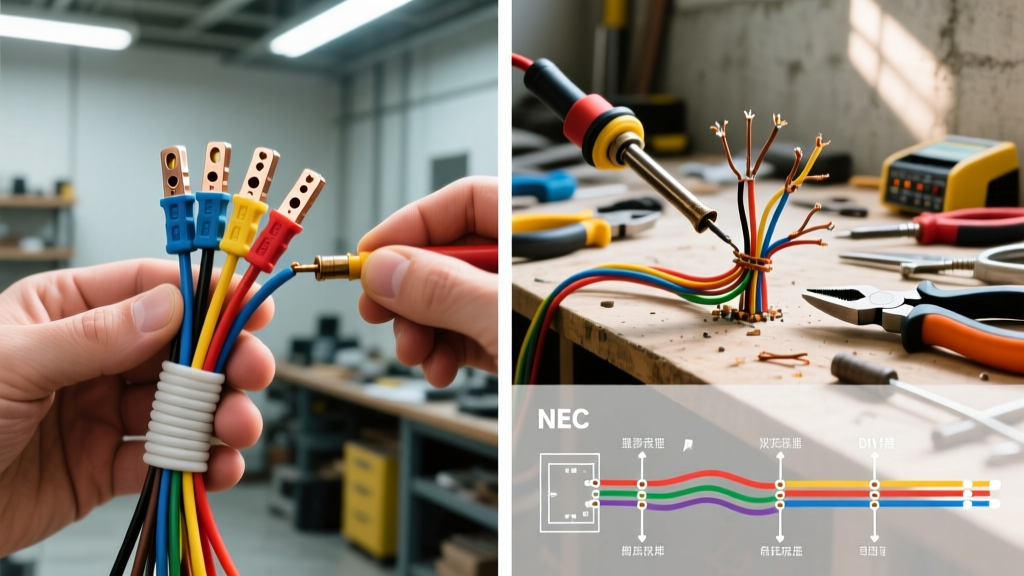
At the heart of every residential and commercial circuit is a fundamental directional flow of electricity. When discussing line vs load electrical wiring, we are defining the origin and destination of electrical current. The line wire (often referred to as the 'hot' or 'source' wire) carries power from the main electrical panel to the device. The load wire carries power from the device to the next fixture or appliance downstream.
While this concept seems straightforward in theory, the physical reality inside a crowded junction box or a multi-gang switch plate is rarely color-coded perfectly. Misidentifying these conductors is one of the most common causes of tripped breakers, destroyed smart home equipment, and severe electrical shock hazards. This analysis breaks down how DIY enthusiasts and licensed electricians approach line and load identification, highlighting the critical gaps in tooling, methodology, and risk tolerance.
The Tooling Gap: How DIYers and Pros Test for Voltage
The most glaring difference between a weekend warrior and a journeyman electrician is the reliance on testing equipment. Identifying the line wire requires verifying which conductor has live voltage when the circuit is energized and the switch/device is disconnected.
The DIY Approach: Non-Contact Voltage Testers (NCVT)
Most DIYers rely on basic non-contact voltage testers (often called 'tick tracers'). While useful for a quick safety check before touching a wire, NCVTs detect electromagnetic fields, not direct physical voltage. In a crowded box with multiple live circuits, a basic NCVT will often 'ghost' or give false positives on load wires that are running parallel to live line wires. This leads to dangerous misidentifications.
The Professional Approach: Solenoid Testers and Field Meters
Professionals rely on definitive measurement tools. The industry standard is the OSHA-recommended use of categorized multimeters or solenoid voltage testers (commonly known as Wiggys). A pro will typically use a tool like the Fluke T6-1000 (retailing around $230 in 2026) which measures voltage through the insulation without exposed probes, or a Klein Tools NCVT-4IR ($45) which features dual-range sensitivity to isolate specific wires in dense bundles.
Expert Warning: Never rely solely on wire color to identify line vs load. Under the National Electrical Code (NEC), a white wire can be used as a hot line conductor in a switch loop if it is properly re-identified with black tape or paint. Assuming white is always neutral or load is a fatal error.
Real-World Scenarios and Failure Modes
To truly understand the stakes of line vs load electrical wiring, we must examine specific devices where reversing these connections results in distinct failure modes.
Scenario A: GFCI Receptacles (e.g., Leviton 20940-E)
Ground Fault Circuit Interrupters have distinct 'LINE' and 'LOAD' brass and silver terminal screws. The LINE terminals connect to the power source; the LOAD terminals connect to downstream outlets to extend ground-fault protection.
- DIY Failure Mode: If a DIYer reverses the line and load wires on a standard $19 Leviton 20940-E GFCI, the receptacle itself may still power a plugged-in device. However, the internal ground-fault monitoring circuit is bypassed for downstream devices. According to the Electrical Safety Foundation International (ESFI), this creates a hidden hazard where downstream outlets appear protected but will not trip during a ground fault, risking severe electrocution.
- Pro Mitigation: A professional will perform a 'trip test' using a dedicated GFCI receptacle tester (like the Gardner Bender GFI-3501) on downstream outlets after installation to verify the load-side protection is active.
Scenario B: Smart Switches (e.g., Lutron Caseta PD-6ANS)
Smart switches require a continuous low-voltage power source to maintain their internal radio receivers (Zigbee, Z-Wave, or Clear Connect). This requires a line, a load, and crucially, a neutral wire.
- DIY Failure Mode: Confusing the load wire for a neutral wire (both can sometimes be white or bare in older, non-compliant wiring). Connecting the smart switch's neutral pigtail to the load wire will instantly short the circuit, destroying the $65 Lutron Caseta switch and potentially damaging the panel breaker.
- Pro Mitigation: Electricians map the entire circuit, identifying the actual neutral bundle in the back of the box, and use wire nuts to pigtail the smart switch neutral without disturbing the main neutral return path.
The 3-Way Switch Loop Trap
Nowhere is the line vs load distinction more confusing than in 3-way switch configurations. In a standard 3-way setup, power enters at one switch (the line), travels through two 'traveler' wires to the second switch, and then exits to the light fixture (the load).
However, in older 'California 3-way' or alternate wiring methods, the line and load might both enter the same switch box, with travelers running to the second switch. A DIYer attempting to upgrade to a smart 3-way system (like the GE Enbrighten Z-Wave Plus) will often misidentify the travelers as line/load, resulting in a switch that only works when the secondary switch is in a specific position. Professionals solve this by temporarily disconnecting all wires, capping them safely, and using a continuity tester and a tone generator to map the exact path of the travelers versus the true line and load conductors.
Cost, Time, and Risk Matrix
When deciding whether to tackle a line/load wiring project yourself or hire a licensed electrician, consider the following matrix based on 2026 national averages for electrical services.
| Project Scope | DIY Cost (Materials) | Pro Cost (Labor + Materials) | Risk of Line/Load Reversal | Recommendation |
|---|---|---|---|---|
| Single GFCI Replacement | $18 - $25 | $125 - $175 (Minimum service call) | High (Hidden shock hazard) | DIY (if using a plug-in tester to verify) |
| Smart Switch Installation | $40 - $80 | $150 - $225 | Medium (Device destruction) | DIY (if neutral is clearly identified) |
| 3-Way to Smart Switch Upgrade | $90 - $140 | $250 - $350 | High (Complex traveler mapping) | Hire a Professional |
| Panel Sub-feed / Multi-wire Branch | $50 - $100 | $400 - $800+ | Critical (Fire/Arc fault risk) | Hire a Professional |
Professional Step-by-Step Identification Protocol
If you are determined to perform DIY electrical work, you must adopt professional safety and identification protocols. The National Fire Protection Association (NFPA) mandates strict adherence to lockout/tagout and verification procedures in the NEC. Follow this sequence to identify line and load safely:
- Kill the Power and Verify: Turn off the breaker at the main panel. Use a CAT III or CAT IV rated multimeter to test between the suspected hot wire and a known ground. The reading must be exactly 0.0V.
- Disconnect and Separate: Remove the existing switch or receptacle. Untangle the wires and separate them so they are not touching each other or the metal box. Cap any exposed copper with wire nuts.
- Energize and Test (The Line Check): Turn the breaker back on. Using your NCVT or multimeter, carefully probe the separated wires. The single wire that registers 120V (or 240V for heavy appliances) is your LINE. Mark it immediately with black electrical tape.
- Identify the Load: Turn the breaker back off. The wire that leads out to the fixture or downstream outlets is your LOAD. If you have multiple loads, you must map them to their respective breakers.
- Identify the Neutral: Locate the bundle of white wires tied together in the back of the box. Do not untie this bundle unless you are adding a new neutral pigtail.
Code Compliance and the AFCI/GFCI Mandates
Understanding line vs load is not just about making the device work; it is about satisfying the National Electrical Code (NEC). The 2023 NEC (and the upcoming 2026 cycle) heavily expanded the requirements for Arc Fault Circuit Interrupters (AFCIs) and GFCIs in residential dwellings.
When installing an AFCI/GFCI combination breaker in the main panel, the 'load' is the neutral pigtail that must be connected to the panel's neutral bar, while the circuit neutral must connect to the breaker's load terminal. Reversing the line and load neutral connections on a combination breaker will cause it to trip immediately upon energization, or worse, fail to detect parallel arc faults. This level of panel work strictly requires a licensed professional, as the line side of the main panel lugs remains energized even when the main breaker is off.
Final Verdict: When to Call the Pros
Mastering line vs load electrical wiring is the gateway to intermediate home electrical projects. If you are replacing a standard single-pole switch or a single-location GFCI, and you have invested in a quality multimeter and a plug-in circuit tester, DIY is a viable and cost-effective route.
However, if you are dealing with multi-way switch loops, ungrounded older wiring (knob-and-tube or early Romex without a ground), or smart home integrations that require neutral pigtailing in crowded boxes, the risk of misidentifying a load wire as a neutral crosses the threshold from 'frustrating' to 'dangerous.' In these scenarios, the $150 to $250 investment in a licensed electrician guarantees NEC compliance, proper device functionality, and most importantly, the safety of your home's electrical infrastructure.