
The Transition from Prototyping to Compliant Production
Prototyping an LCD display with an Arduino on a solderless breadboard is a fundamental rite of passage for electronics enthusiasts. However, transitioning that same LCD wiring Arduino architecture into a commercial control panel, medical device, or industrial automation environment requires a radical shift in mindset. In professional electrical engineering, a functional circuit is only half the battle; the other half is passing rigorous inspection and compliance audits. When deploying microcontrollers and character displays in the field, inspectors will evaluate your wire harnesses, signal integrity, grounding schemes, and enclosure safety against established industrial standards.
This guide bridges the gap between hobbyist tutorials and professional panel building. We will explore how to wire standard HD44780-based LCDs (via I2C or parallel) to Arduino ecosystems—such as the Arduino Opta or Mega 2560—while strictly adhering to NEC, UL, and IPC compliance frameworks relevant in 2026.
Regulatory Framework: NEC, UL, and IPC Standards
Before cutting a single wire, you must understand the regulatory environment governing low-voltage control circuits. Unlike 120V/240V AC mains wiring, Arduino and LCD setups typically operate at 5V DC or 3.3V DC. However, this does not exempt them from inspection.
Key Compliance Standards:
1. NEC Article 725: Covers Class 1, Class 2, and Class 3 remote-control, signaling, and power-limited circuits. Most Arduino LCD setups powered by a UL-listed, power-limited supply (e.g., a 5V 2A Mean Well HDR-15-5) qualify as Class 2 circuits, which relaxes some Chapter 3 wiring methods but mandates specific separation from high-voltage conductors.
2. IPC/WHMA-A-620: The definitive industry standard for cable and wire harness assemblies. Inspectors use this to evaluate crimp quality, strain relief, and wire routing.
3. IEC 61010-1 / UL 61010-1: Safety requirements for electrical equipment for measurement, control, and laboratory use, dictating creepage and clearance distances inside the enclosure.
For a deeper understanding of low-voltage signaling circuit codes, refer to the NFPA National Electrical Code (NEC) documentation regarding Article 725.
Component Specification Matrix: Hobbyist vs. Industrial
Consumer-grade components often fail under the thermal and vibrational stresses of industrial environments. The table below contrasts standard prototyping parts with inspection-compliant alternatives.
| Component Category | Hobbyist / Prototyping Grade | Industrial / Compliant Grade | Compliance & Inspection Benefit |
|---|---|---|---|
| Microcontroller | Arduino Uno R3 ($28) | Arduino Opta / Portenta ($150-$220) | DIN-rail mountable, UL-recognized, 24V DC tolerant I/O. |
| LCD Module | Standard 16x2 HD44780 (0°C to 50°C) | Industrial 20x4 Extended Temp (-20°C to 70°C) | Prevents liquid crystal freezing/blackouts in unclimate-controlled panels. |
| Power Supply | USB Wall Wart (5V) | Mean Well DR-15-5 (5V 3A) ($22) | UL/CE listed, Class 2 power-limited, short-circuit protection. |
| Wire Harness | Jumper Wires (Dupont) | 24 AWG Stranded, Belden 8723 ($1.50/ft) | Shielded twisted pair (STP) prevents EMI; meets IPC-A-620. |
| Termination | Soldered / Bare Wire | Phoenix Contact Ferrules (AI 0.5-8 WH) | Prevents strand fraying; ensures consistent terminal block torque. |
I2C Bus Wiring: Overcoming the 400pF Capacitance Limit
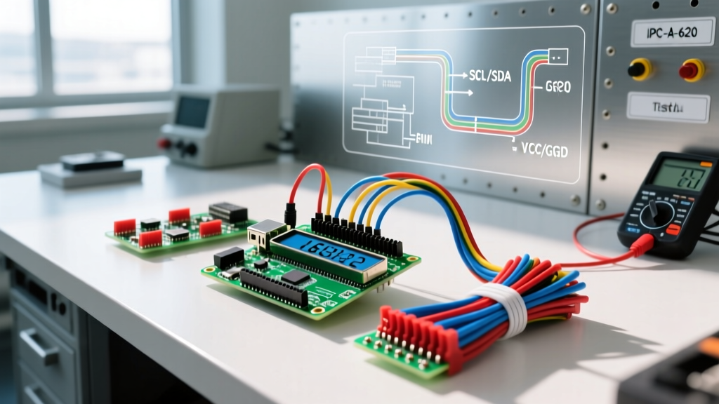
The most common method for LCD wiring Arduino setups in modern panels is using a PCF8574T I2C backpack. This reduces the connection to four wires: VCC, GND, SDA, and SCL. While electrically simple, I2C is highly susceptible to electromagnetic interference (EMI) and bus capacitance in long wire runs.
The Physics of I2C Failure in Control Panels
According to the Arduino Wire/I2C Library Documentation, the I2C bus has a strict maximum capacitance limit of 400pF. Standard 24 AWG unshielded wire exhibits roughly 15pF to 20pF per foot of capacitance. If you route an unshielded I2C cable near a VFD (Variable Frequency Drive) or a 120V AC contactor, the parasitic capacitance and inductive coupling will corrupt the SDA/SCL clock edges, resulting in LCD bus lockups or garbled characters.
Compliant Wiring Solution: Use Belden 8723 (or equivalent) shielded twisted-pair cable. Twist the SDA and SCL lines together to reject common-mode noise. Connect the drain wire to the chassis ground at one end only (typically the Arduino/PLC end) to prevent ground loops. For runs exceeding 1 meter, consider adding a PCA9600 I2C bus extender or utilizing differential I2C transceivers (like the P82B715) to maintain signal integrity and pass EMC emissions testing.
Step-by-Step Compliant Harness Fabrication
To satisfy an IPC-A-620 Rev E certified inspector, your wire harnesses must demonstrate professional termination and strain relief. Follow this fabrication protocol:
- Wire Cutting and Stripping: Cut the Belden 8723 to length, allowing 10% extra for routing service loops. Use a precision thermal wire stripper to remove exactly 8mm of insulation without nicking the 24 AWG copper strands. Nicked strands reduce tensile strength and fail IPC pull-test requirements.
- Ferrule Crimping: Slide a Phoenix Contact AI 0.5-8 WH (white, 24 AWG) ferrule over the stripped end. Use a calibrated ratcheting crimp tool (e.g., WireFerrule HSC8 6-4). The crimp must be gas-tight; a proper ratcheting tool ensures the exact compression force is applied every time.
- Shield Termination: Strip back the outer jacket, fold the braided shield and drain wire back over the jacket, and secure it with copper foil tape or a dedicated shield-clamp terminal block. Never leave a drain wire 'pigtailed' and floating.
- Panel Routing: Route the low-voltage LCD harness in a dedicated slotted wiring duct, physically separated from AC mains wiring by at least 2 inches (or a grounded metal divider) to satisfy NEC Article 725 separation rules.
For comprehensive harness acceptance criteria, panel builders should consult the IPC/WHMA-A-620 Standard guidelines regarding crimp visibility and insulation displacement.
The Inspector's Checklist: Common Failure Modes
When a third-party inspector or lead electrical engineer reviews your LCD wiring Arduino control panel, they will look for specific edge cases and failure modes. Use this checklist before powering up the system:
- Terminal Block Torque: Are the screw terminals tightened to the manufacturer's specification (usually 0.4 Nm to 0.6 Nm for 24 AWG)? Loose connections cause high resistance, leading to voltage drops that brown out the LCD backlight.
- Bend Radius Violations: Has the wire harness been bent tighter than 4x its outer diameter? Sharp bends crush the internal dielectric, altering the impedance and capacitance of the I2C lines.
- Backlight Current Draw: A standard 20x4 LCD backlight can draw up to 250mA. If wired through a long, thin gauge harness, the voltage at the LCD VCC pin may drop below 4.5V, causing the HD44780 controller to reset unpredictably. Inspectors will measure the voltage at the display pins under full backlight load.
- Creepage and Clearance: If the Arduino is powered directly from a non-isolated buck converter tied to mains voltage, the clearance between the high-voltage AC traces and the low-voltage DC LCD header must meet IEC 61010-1 standards (typically >4mm for pollution degree 2). Using an isolated, UL-listed DIN-rail power supply eliminates this risk entirely.
- Strain Relief: Is there a mechanical clamp or zip-tie anchor securing the wire harness within 2 inches of the LCD PCB header? Relying solely on the solder joints or Dupont pins for mechanical support is an automatic IPC failure.
Troubleshooting Field Deployments
Even with perfect bench testing, field deployments introduce new variables. A frequent issue in industrial LCD wiring Arduino setups is ground bounce. When heavy inductive loads (like solenoids or relays) switch off, the resulting flyback voltage can momentarily elevate the local ground plane. If the Arduino and the LCD share a thin ground wire, this bounce can exceed the logic threshold of the I2C bus, causing the microcontroller to misinterpret a '0' as a '1'.
The Fix: Implement a star-grounding topology. Run a dedicated, heavy-gauge (18 AWG) ground wire directly from the main DIN-rail ground bus to the Arduino GND, and a separate, dedicated ground wire to the LCD GND. Do not daisy-chain grounds through the delicate signal headers. Additionally, place a 100µF low-ESR ceramic capacitor and a 0.1µF bypass capacitor directly across the VCC and GND pins on the rear of the LCD PCB to buffer transient current demands from the backlight LEDs.
Conclusion
Executing a compliant LCD wiring Arduino project requires looking beyond the schematic. By selecting industrial-rated components, adhering to NEC Class 2 separation rules, fabricating harnesses to IPC-A-620 standards, and respecting the physical limitations of the I2C bus, you transform a fragile prototype into a robust, inspection-ready control interface. In the realm of commercial electrical wiring, reliability is not an accident; it is the direct result of rigorous adherence to established engineering standards.