
Understanding L1 L2 L3 Electrical Wiring in Modern Power Systems
When working with commercial, industrial, or heavy residential power systems, understanding l1 l2 l3 electrical wiring is fundamental to safety, code compliance, and equipment longevity. In three-phase power distribution, L1, L2, and L3 represent Line 1, Line 2, and Line 3—the three active, current-carrying conductors that deliver alternating current offset by 120 electrical degrees. While North American electricians historically referred to these as Phase A, Phase B, and Phase C, the global shift toward standardized nomenclature and the harmonization of international codes have made the L1/L2/L3 designation ubiquitous in modern schematics and variable frequency drive (VFD) manuals.
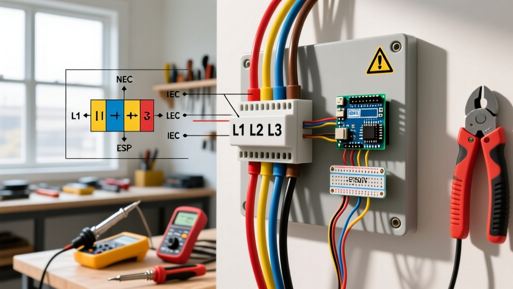
However, the physical execution of l1 l2 l3 electrical wiring varies drastically depending on your jurisdiction. The North American National Electrical Code (NEC) and the International Electrotechnical Commission (IEC) standards dictate entirely different color-coding schemes, voltage baselines, and labeling requirements. Misidentifying these phases during a panel termination or motor connection can result in catastrophic equipment failure, severe arc flash incidents, or immediate code violations during municipal inspections.
The Core Standards: NEC vs. IEC Phase Identification
One of the most common pitfalls for international contractors or engineers reading foreign schematics is assuming phase colors are universal. They are not. The NFPA 70 (National Electrical Code) mandates specific color codes based on the system voltage, whereas the IEC 60445 standard enforces a single, universal color palette for all three-phase systems regardless of voltage.
| Conductor | NEC 208Y/120V | NEC 480Y/277V | IEC 60445 (All Voltages) |
|---|---|---|---|
| L1 (Line 1) | Black | Brown | Brown |
| L2 (Line 2) | Red | Orange | Black |
| L3 (Line 3) | Blue | Yellow | Grey |
| Neutral (N) | White or Grey | White or Grey | Blue |
| Ground (PE) | Green, Green/Yellow, or Bare | Green, Green/Yellow, or Bare | Green/Yellow |
Note: In Canada, the CSA C22.1 (Canadian Electrical Code) aligns closely with the NEC but utilizes Red, Black, and Blue for 600V systems, which differ from the US 480V standards.
Decoding L1 L2 L3 Electrical Wiring Configurations
Wye (Star) vs. Delta Connections
The physical arrangement of the transformer secondary windings dictates how L1, L2, and L3 behave relative to ground and neutral. In a Wye (Y) configuration, such as a standard 208Y/120V or 480Y/277V system, the three phases meet at a common neutral point. This allows you to pull 120V (or 277V) from any single line (L1, L2, or L3) to Neutral, and 208V (or 480V) phase-to-phase. This is the dominant configuration for modern commercial buildings because it natively supports both heavy HVAC loads and standard single-phase lighting.
Conversely, a Delta (Δ) configuration connects the phases in a triangle. There is no inherent neutral point. Delta systems, like 240V Delta or 480V Delta, are primarily used in older industrial facilities or specific manufacturing plants where high starting torque for heavy machinery is required. In an ungrounded 480V Delta system, a phase-to-ground fault on L1 will not trip a standard breaker immediately; instead, it shifts the reference ground, requiring specialized ground-fault indication systems to detect the anomaly before a second fault causes a catastrophic phase-to-phase short.
Code Compliance: Tagging, Labeling, and Re-Identification
Under NEC Article 210.5(C) for branch circuits and 215.12(C) for feeders, you are legally required to identify phase conductors consistently throughout the entire premises. If your facility uses 208Y/120V, L1 must be Black, L2 must be Red, and L3 must be Blue everywhere. You cannot use Black for L1 in Panel A and Black for L2 in Panel B.
The Reality of Field Wiring and Phase Tape
In real-world remodels, pulling perfectly colored THHN/THWN-2 wire from a distributor is not always possible due to supply chain shortages. If you are forced to pull a 4-conductor SOOW flexible cord or use available wire colors that do not match the NEC mandate, you must re-identify the conductors at every termination point. According to NEC 200.7 and 210.5, this re-identification must be permanent.
- Approved Method: Using high-quality vinyl phase tape, such as 3M Scotch 35 Series Color Coding Tape (typically $3.50 to $5.00 per roll). Wrap the tape completely around the conductor insulation at least twice, extending slightly past the stripping point.
- Prohibited Method: Using colored sharpies, paint markers, or standard black electrical tape wrapped over a white neutral to make it a 'hot' conductor in a conduit. Inspectors will immediately red-tag this as a violation.
Expert Insight: When terminating L1, L2, and L3 into a heavy-duty safety switch or VFD, always leave 6 to 8 inches of slack and apply phase tape before stripping the wire. Stripping the wire first and then taping often results in tape bridging the bare copper, which can cause a dead short if the tape degrades under the high thermal stress of a 75°C termination lug.
Common Edge Cases and Failure Modes in 3-Phase Panels
The High-Leg Delta (Wild Leg) Hazard
One of the most dangerous configurations in North American l1 l2 l3 electrical wiring is the 240V Center-Tapped Delta, commonly known as the High-Leg, Wild-Leg, or Stinger Delta. In this setup, the transformer winding between L1 and L3 is center-tapped and grounded to create a Neutral.
This yields 120V from L1-to-Neutral and 120V from L3-to-Neutral. However, the voltage from L2-to-Neutral is 208V. If an electrician mistakenly lands a standard 120V single-pole breaker on the L2 busbar, the connected appliances will instantly receive 208V, resulting in immediate destruction of the load and a severe fire hazard. NEC 110.15 strictly mandates that the high-leg (L2) must be identified by the color Orange. Furthermore, NEC 408.3(E) requires the high-leg to be placed on the 'B' phase position (the center phase) in panelboards to prevent accidental single-pole breaker placement.
Phase Rotation and Motor Burnout
In three-phase motors, the sequence of the voltage waveforms reaching the windings determines the direction of rotation. An L1-L2-L3 sequence will spin a motor clockwise. If the wiring is swapped to L1-L3-L2, the motor will spin counter-clockwise. In applications like centrifugal pumps, scroll compressors, or cooling tower fans, reverse rotation can cause catastrophic mechanical failure, cavitation, or immediate overheating within minutes.
Step-by-Step Verification Using a Phase Rotation Meter
Never rely on visual wire tracing alone to confirm L1 L2 L3 sequence. Always verify with a dedicated phase rotation meter, such as the Fluke 1130 or the Extech PR100 (priced around $150-$250). Follow this procedure to ensure compliance and safety:
- De-energize and Lockout: Ensure the main disconnect is off and apply your personal padlock (LOTO) before connecting test leads to the busbars or motor terminals.
- Connect the Leads: Attach the meter's L1, L2, and L3 clips to the corresponding line-side terminals of the disconnect switch.
- Energize the Circuit: Remove LOTO and safely close the disconnect switch while standing to the side (arc flash boundary protocol).
- Read the Indicator: Observe the meter's LED or LCD display. A clockwise arrow or 'CW' indicator confirms an L1-L2-L3 positive sequence. A counter-clockwise indicator means two phases are swapped.
- Correct and Re-test: If the sequence is reversed, de-energize, swap any two line conductors (e.g., swap L1 and L2), and repeat the test until the correct sequence is achieved.
For deeper diagnostic insights on rotating fields, Fluke's technical guides on phase rotation provide excellent visual breakdowns of how swapped phases affect induction motor slip and torque curves.
Frequently Asked Questions (FAQ)
Can I use L1, L2, and L3 for single-phase 240V circuits?
Technically, no. In a standard North American single-phase 240V/120V split-phase system, the two hot legs are derived from a single transformer winding and are 180 degrees out of phase. The NEC designates these as Line 1 and Line 2 (or simply the two ungrounded conductors). L3 is strictly reserved for three-phase systems. Using L3 terminology on a residential single-phase panel will confuse inspectors and future technicians.
What happens if I mix IEC and NEC color codes in the same panel?
This is a severe code violation. If you are integrating imported European machinery (wired with IEC Brown/Black/Grey) into a US facility (NEC Black/Red/Blue), you must re-identify the conductors at the machine's disconnect switch to match the facility's NEC color scheme. You cannot mix IEC Grey (L3) and NEC Blue (L3) in the same conduit run.
Do smart panels and IoT breakers change how L1/L2/L3 are monitored?
Modern IoT-enabled panelboards, such as the Schneider Electric PowerTag or Eaton Brightlayer systems, utilize internal current transformers (CTs) on each individual busbar. While the physical l1 l2 l3 electrical wiring remains bound by traditional code, these smart systems allow facility managers to monitor phase imbalance, harmonic distortion, and power factor on L1, L2, and L3 independently via cloud dashboards, alerting engineers to voltage sags before they trip sensitive VFDs.