
Understanding the White, Black, and Red Wire Topology
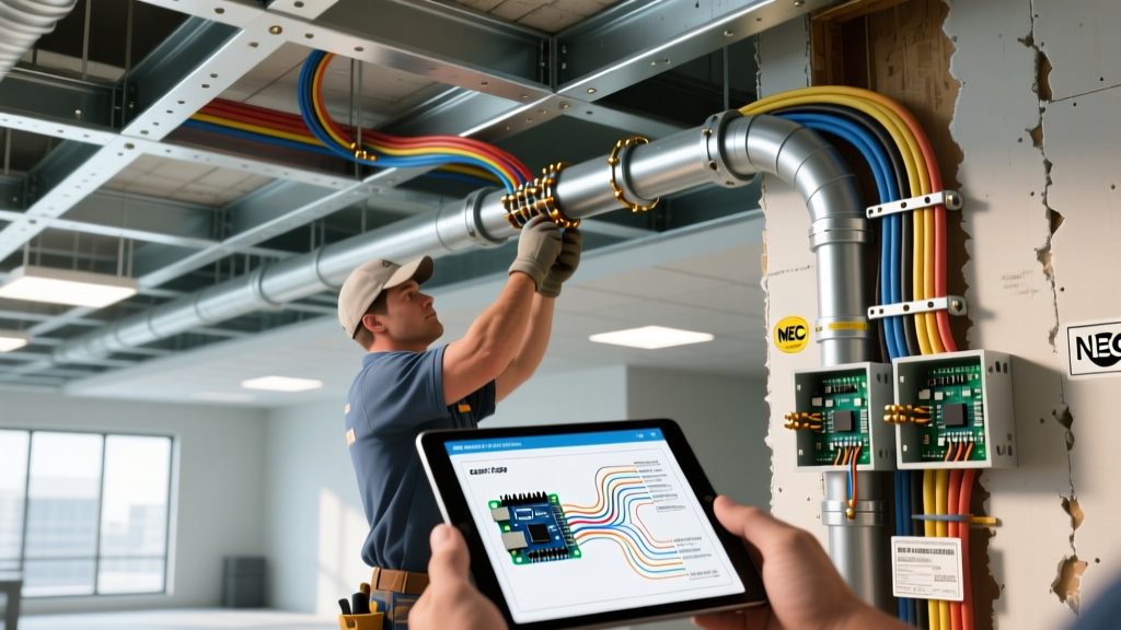
When you open a junction box, ceiling canopy, or breaker panel and encounter a 12/3 or 14/3 NM-B cable (commonly referred to by the brand name Romex), the presence of black, red, and white wires indicates a multi-conductor circuit. Troubleshooting electrical wiring white black red configurations requires more than just a basic understanding of hot and neutral; it demands that you first identify the specific circuit topology. In modern residential and commercial construction, this three-wire setup is almost exclusively used for one of three applications: Multi-Wire Branch Circuits (MWBC), 3-way switch loops, or dedicated 240V appliance feeds.
Misdiagnosing the circuit type is the leading cause of electrical fires and equipment destruction in DIY and junior electrician troubleshooting. A white wire is not always a neutral, and a red wire is not always a secondary hot. This comprehensive guide will walk you through the exact diagnostic procedures, voltage matrices, and failure modes associated with these specific wire colors, ensuring you can isolate faults safely and accurately.
Essential Diagnostic Tools for 3-Wire Circuits
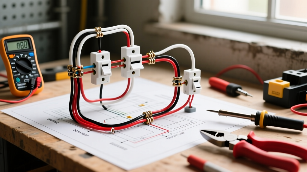
Before touching any wire, you must verify the absence of voltage and map the circuit behavior. Relying on a simple neon screwdriver tester is insufficient for 3-wire diagnostics. You need equipment that can measure potential differences between multiple conductors simultaneously.
- True-RMS Digital Multimeter: The Fluke 117 (approx. $200) or the Klein Tools MM400 (approx. $55) are industry standards. True-RMS is critical for accurately reading voltage on circuits with non-linear loads like LED drivers or smart switches.
- Non-Contact Voltage Tester (NCVT): The Klein NCVT-2 detects both standard 120V and 240V ranges, helping you identify which wires are energized before making contact.
- Receptacle Tester with GFCI/AFCI: Useful for quickly identifying open neutrals or crossed hot/neutral pairs at the termination point.
- Lockout/Tagout (LOTO) Kit: Never troubleshoot a live panel without proper LOTO procedures in place, as mandated by OSHA safety standards.
The Voltage Matrix: Identifying Your Circuit Topology
The fastest way to determine what your black, red, and white wires are doing is to measure the voltage between them at the termination point (with the circuit energized and loads connected). Use the matrix below to identify your circuit type.
| Test Points | MWBC (Correctly Wired) | MWBC (Same-Phase Error) | 3-Way Switch Loop | 240V Appliance (No Neutral) |
|---|---|---|---|---|
| Black to Red | 240V | 0V | 120V or 0V (Travelers) | 240V |
| Black to White | 120V | 120V | 120V or 0V | 120V (White is Hot) |
| Red to White | 120V | 120V | 120V or 0V | 120V (White is Hot) |
Note: In a 3-way switch loop, voltages will fluctuate between 120V and 0V depending on the physical toggle position of the switches.
Scenario 1: Troubleshooting Multi-Wire Branch Circuits (MWBC)
An MWBC uses the black and red wires as two separate 120V 'hot' legs originating from opposite phases (Phase A and Phase B) of the electrical panel. The white wire serves as a shared neutral. Because the two hot legs are 180 degrees out of phase, the return current on the white neutral cancels out, meaning the neutral only carries the difference in current between the two legs.
Critical Failure Mode: The 'Same-Phase' Breaker Error
The most dangerous fault in an MWBC occurs when an installer places both the black and red pigtails on breakers that share the same phase leg. If Black and Red are on the same phase, the voltage between them reads 0V. Consequently, the neutral current does not cancel out; it accumulates. If you draw 15A on the black wire and 15A on the red wire, the shared 14 AWG white neutral will carry 30A. This will melt the wire insulation inside your walls long before the 15A breakers trip, creating a severe fire hazard.
Step-by-Step MWBC Triage
- Verify Phase Opposition: With the panel cover removed (using extreme caution and PPE), measure the voltage between the black breaker terminal and the red breaker terminal. It must read 240V. If it reads 0V, move one breaker to the opposite side of the panel bus bar.
- Check for Handle Ties: The National Fire Protection Association (NFPA) mandates in NEC Article 210.4 that all MWBCs must have a simultaneous disconnect mechanism. Verify that a listed handle tie (e.g., Siemens Q21520 or Eaton THQL1X2) or a common-trip 2-pole breaker is installed. This prevents a maintenance worker from turning off the black circuit while the red circuit remains live, which would energize the shared neutral.
- Test for Lost Neutral: If your 120V appliances are experiencing wild voltage fluctuations (e.g., lights glowing blindingly bright while others dim), you have a 'lost neutral' fault. The white wire has disconnected somewhere in the daisy chain. Immediately shut off both breakers and trace the white wire continuity back to the panel.
NEC Code Alert: According to NEC Article 210.4(D), the grounded (neutral) conductor of a multiwire branch circuit must be provided with a means to identify it at each termination point. If you are troubleshooting an older home and the white wires are mixed in a bundle, use a tone generator to map the exact MWBC neutral to its corresponding hots.
Scenario 2: Troubleshooting 3-Way Switch Loops
In a 3-way switch configuration, the black, red, and white wires are used to route power between two switches that control a single light fixture. In this topology, the concept of 'neutral' often changes entirely. The white wire is frequently used as a 'traveler' or a 'switched hot', not a neutral.
Identifying the Terminals
A standard 3-way switch features three terminals: one 'Common' (usually a dark-colored screw) and two 'Travelers' (usually brass-colored screws). The most common troubleshooting error is misidentifying the Common terminal when replacing a faulty switch.
- The Line/Load Wire: Usually connects to the Common screw. This is the constant hot feed from the panel or the switched hot going up to the light fixture.
- The Travelers: The red and black (or red and white) wires connect to the brass screws. They carry the alternating hot current between the two switches.
Diagnosing a Dead 3-Way Circuit
If a newly installed 3-way switch only works when the other switch is in a specific position, you have crossed the travelers with the common wire. The Fix: Turn off the breaker. Disconnect all three wires from the switch. Use your multimeter's continuity setting. Identify the wire that shows continuity to the light fixture (or constant hot from the panel). That wire must go to the dark Common screw. The remaining two wires are your travelers and can be placed on either brass screw. Furthermore, per NEC Article 200.7(C)(2), if the white wire is being used as a traveler or a hot feed, it must be permanently re-identified with black electrical tape or marker at both termination points to warn future electricians that it is not a neutral.
Scenario 3: 240V Appliance Circuits (Baseboard Heaters & HVAC)
When wiring pure 240V loads like electric baseboard heaters, water heaters, or older HVAC condenser units, a neutral is not required. Electricians will often use 12/2 or 10/2 cable, but if 12/3 or 10/3 cable is pulled through the walls, the red, black, and white wires will all be present.
The 'Re-Identified White' Fault
In a pure 240V circuit utilizing 3-wire cable, the black and red wires serve as the two 120V hot legs (yielding 240V across them). The white wire is capped off and abandoned in the back of the box, or it is used as a hot leg if only a 2-wire cable was available and the installer used the white wire as the second hot. If you measure 120V from Black to White and 120V from Red to White, but 240V from Black to Red, and the white wire is connected to a terminal on the appliance, the installer has illegally used the white wire as a hot conductor without re-identification. While the appliance may function, this violates electrical codes and poses a severe shock hazard to anyone who assumes the white wire is safe to touch. Cap the white wire with a wire nut and ensure the appliance is fed strictly by the black and red conductors.
Safety Protocols and Final Verification
Troubleshooting multi-wire circuits inherently involves interacting with 240V potential, which is significantly more lethal than standard 120V circuits. The Occupational Safety and Health Administration (OSHA) strictly enforces arc flash and shock hazard boundaries. Always wear voltage-rated gloves and safety glasses when performing live-dead-live testing on MWBC panels.
Once you have isolated the fault—whether it is installing a missing handle tie on an MWBC, correcting traveler terminals on a 3-way switch, or capping an abandoned neutral on a 240V feed—perform a final load test. Use a clamp meter to verify that the current on the white neutral wire in an MWBC does not exceed the rating of the breaker under maximum simultaneous load conditions. By systematically applying the voltage matrix and respecting the specific NEC articles governing these conductors, you can resolve complex wiring faults safely and permanently.