
The Hidden Costs of Poor Servo Arduino Wiring
Wiring a servo motor to an Arduino seems trivial on the surface: connect the signal pin, route the power, and upload the standard Sweep sketch. However, moving from a single micro-servo on a breadboard to a multi-axis robotic arm or RC vehicle introduces severe electrical challenges. The most common failure modes—erratic jitter, microcontroller brownouts, and burnt-out voltage regulators—are rarely coding errors. They are almost exclusively servo Arduino wiring and material failures.
This guide strips away the guesswork. As a material and tool guide, we will detail the exact wire gauges, connector ecosystems, power delivery components, and crimping tools required to build robust, vibration-resistant servo harnesses in 2026.
Wire Selection: Gauge, Material, and Strand Count
The stock wires included with hobby servos are notoriously inadequate for anything beyond bench testing. A standard SG90 micro-servo comes with 26 AWG wire, while a high-torque MG996R might include 22 AWG. When building custom harnesses, you must upgrade based on current draw and flexibility requirements.
Silicone vs. PVC Insulation
Always choose stranded silicone wire over standard PVC hook-up wire for servo applications. Silicone insulation withstands soldering temperatures up to 200°C without melting back, and it remains highly flexible at room temperature. This flexibility is critical; stiff PVC wires transfer mechanical vibration directly into the solder joints and crimp terminals, leading to micro-fractures over time.
Wire Gauge Matrix for Servo Harnesses
| Wire Gauge (AWG) | Max Continuous Current | Best Use Case | Servo Compatibility |
|---|---|---|---|
| 26 AWG | 1.5A | Signal lines only | SG90, MG90S (Micro) |
| 22 AWG | 3.0A | Standard power & signal | Standard 9g to 25g servos |
| 18 AWG | 7.0A | Main power distribution | MG996R, DS3218 (High-Torque) |
| 16 AWG | 10.0A | Battery to BEC/PDU routing | Multi-servo parallel buses |
Pro Tip: For high-torque servos like the DS3218 (which can spike to 4A under stall conditions), use 18 AWG silicone wire for the power and ground lines, but you can safely step down to 22 AWG for the PWM signal line to save weight and maintain flexibility at the connector.
The Connector Ecosystem: Ditching Dupont
The standard black 'Dupont' connectors found in beginner kits are the leading cause of intermittent signal loss in robotics. They rely on friction, lack a positive locking mechanism, and their thin stamped brass contacts degrade rapidly under vibration.
Recommended Connector Standards
- JST-XH (2.54mm Pitch): The gold standard for custom servo Arduino wiring. The 2.54mm pitch matches standard Arduino headers and 0.1-inch perfboards perfectly. The housing features a positive friction lock that prevents vibration-induced back-out.
- JST-PH (2.0mm Pitch): Ideal for compact, high-density boards where space is at a premium. Commonly used in modern commercial drone flight controllers and compact Arduino shields.
- Screw Terminal Blocks (3.5mm Pitch): Best for permanent installations where the Arduino is mounted to a chassis and the servo wires need to be field-replaceable without soldering.
Material Cost Reality: A bag of 500 JST-XH housings and pre-tinned crimp pins costs roughly $12 in 2026. The slight premium over Dupont connectors pays for itself immediately by eliminating hours of troubleshooting phantom signal drops.
Power Delivery: Escaping the Arduino 5V Pin Trap
The most critical mistake in servo Arduino wiring is powering the servo directly from the Arduino's 5V pin. The Arduino Uno's onboard linear regulator can safely dissipate only about 800mA of continuous current (and much less if the input voltage exceeds 9V). A single MG996R servo draws 500mA at idle and spikes to 2.5A during a stall. This massive current draw will instantly collapse the Arduino's voltage rail, triggering a brownout reset.
External Power Injection Materials
To wire servos correctly, the power must bypass the Arduino entirely, sourced from an external supply. Here are the materials you need based on your project scale:
- LM2596 Buck Converter Module ($2 - $4): Step down a 12V battery to a stable 5V or 6V for the servo power rail. Ensure you buy the version with an adjustable potentiometer and a digital display to dial in exactly 5.1V to compensate for wire voltage drop.
- PCA9685 PWM Driver Board ($8 - $12): If you are wiring more than four servos, abandon the Arduino's hardware timers. The Adafruit PCA9685 Shield handles the high-current PWM generation via I2C, featuring dedicated screw terminals for external servo power injection.
- Electrolytic Capacitors (470µF, 10V): Servos are inductive loads. When the internal DC motor brakes, it generates a flyback voltage spike. Soldering a 470µF capacitor across the 5V and GND rails at the servo power distribution point absorbs these spikes, protecting your microcontroller.
The Common Ground Mandate
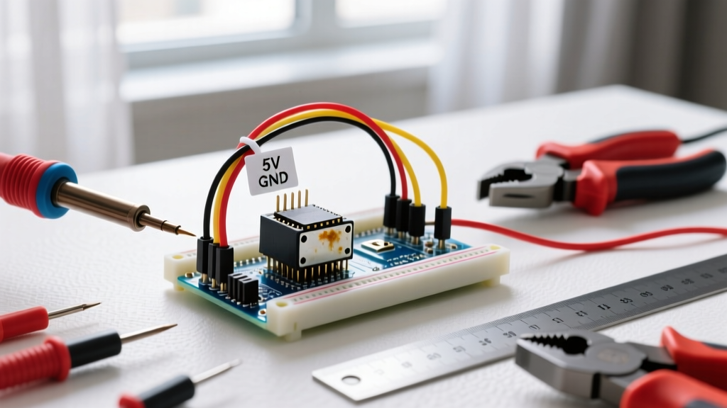
When using an external power supply for your servos, you must wire the ground (GND) of the external power supply directly to an Arduino GND pin. The PWM signal wire relies on a shared voltage reference. Without a common ground, the Arduino's 5V logic signal is floating relative to the servo's power supply, resulting in violent, unpredictable servo twitching. Refer to the SparkFun Servo Hookup Guide for visual diagrams on common ground topologies.
Essential Tools for Harness Fabrication
Building reliable JST-XH or JST-PH harnesses requires specialized tooling. Pliers and generic crimpers will crush the delicate servo terminals, leading to high-resistance connections that melt under load.
- Engineer PA-09 Crimping Tool ($28): This Japanese-made precision crimper is mandatory for JST-XH and JST-PH terminals. It features a ratcheting mechanism that ensures the exact compression depth required for a gas-tight crimp without damaging the wire strands.
- Hakko FX-888D Soldering Station ($110): While crimping is preferred for terminals, you will need to solder capacitors and distribution boards. The FX-888D with a T18-B (conical) tip provides the rapid thermal recovery needed to solder 18 AWG silicone wire without burning the insulation.
- Wire Strippers (20-30 AWG): Use automatic wire strippers calibrated specifically for silicone wire. Standard heavy-duty strippers will nick the fine copper strands of 22 AWG silicone wire, reducing its current capacity and creating a mechanical weak point.
Troubleshooting Matrix: Wiring-Induced Failure Modes
When your servos misbehave, use this diagnostic matrix to identify the physical wiring fault before blaming your code.
| Symptom | Likely Wiring Fault | Material / Tool Fix |
|---|---|---|
| Arduino resets when servo moves | Voltage brownout due to high stall current pulling down the 5V rail. | Separate servo power via LM2596 buck converter; tie GNDs. |
| Servo twitches randomly at idle | Missing common ground between Arduino and external PSU. | Run a dedicated 22 AWG ground wire from PSU to Arduino GND. |
| Servo jitters under load | Voltage drop across undersized wires or poor crimps. | Upgrade to 18 AWG silicone wire; re-crimp with Engineer PA-09. |
| Servo hums but won't move | Signal wire disconnected or broken internally. | Check continuity on PWM wire; replace Dupont with JST-XH. |
Final Assembly Protocol
For a permanent robotic installation, follow this sequence: First, crimp all JST-XH terminals and verify the pull-test (a proper crimp should withstand a 5lb pull without slipping). Second, route your 18 AWG power distribution bus and solder your 470µF buffering capacitors. Third, connect the common ground to the Arduino. Finally, connect the PWM signal wires to your digital pins or PCA9685 board. By treating servo Arduino wiring as a disciplined electrical engineering task rather than an afterthought, you guarantee smooth, reliable actuation for the lifespan of your project.