
The Hidden Dangers of Improper Ceiling Light Electrical Wiring
Every year, electrical malfunctions cause thousands of residential fires, resulting in billions of dollars in property damage. According to the U.S. Consumer Product Safety Commission (CPSC), faulty wiring and improper fixture installations are among the leading culprits. When executing ceiling light electrical wiring, the margin for error is effectively zero. In 2026, the proliferation of smart lighting, integrated LED drivers, and high-draw dimming circuits has made proper installation more complex—and more critical—than ever. This guide details the uncompromising safety protocols, National Electrical Code (NEC) requirements, and professional-grade techniques required to wire ceiling fixtures safely and reliably.
Phase 1: Establishing a Zero-Energy State
Before removing a single canopy screw, you must establish a verified zero-energy state. Relying solely on a wall switch is a fatal mistake; switches often break only the hot leg, leaving the neutral and potentially the fixture itself energized if a reverse-polarity fault exists upstream.
The Professional Lockout/Tagout (LOTO) Approach
While the Occupational Safety and Health Administration (OSHA) mandates strict Lockout/Tagout procedures for commercial environments, residential DIYers and electricians must adopt a similar mindset. Turn off the breaker at the main panel and apply a physical lock or a prominent warning tag. Next, verify the absence of voltage using a Category III (CAT III) or Category IV (CAT IV) non-contact voltage tester (NCVT). The Fluke 2AC-II VoltAlert (retailing around $38) is an industry standard because it features a continuous self-test function, ensuring the tool itself has not failed before you trust it with your life. Always test the NCVT on a known live source, test the target ceiling wires, and then test the known live source again to confirm the tool is still operational.
Phase 2: Junction Box Selection and NEC Fill Calculations
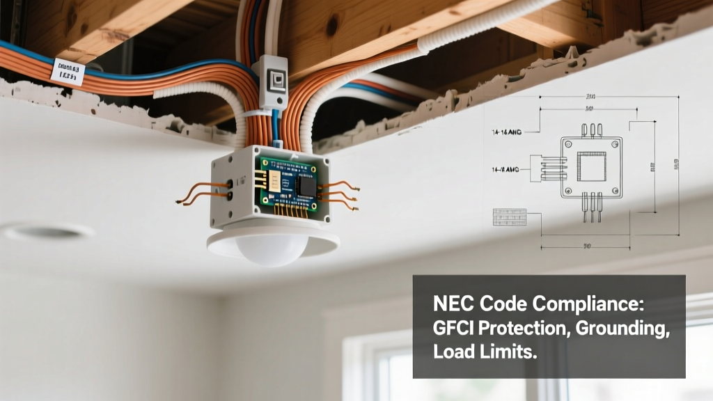
The junction box is the structural and electrical heart of your ceiling light electrical wiring. The National Fire Protection Association (NFPA) outlines strict rules in NEC Article 314 regarding box volume and weight support. Undersized boxes lead to cramped wires, damaged insulation, and excessive heat buildup.
| Box Type / Model | Volume (cu in) | Max Weight Support | Best Use Case | Approx. Cost (2026) |
|---|---|---|---|---|
| Carlon B618R-UPC (Round Old Work) | 18.0 | 50 lbs (with proper joist mounting) | Standard flush-mount LED conversions | $4.50 |
| Arlington BE-1 (Brace & Box Kit) | 15.5 | 50 lbs (spans up to 24" joists) | Heavy chandeliers & ceiling fans in finished ceilings | $22.00 |
| Allied Moulded 4" Round (New Work) | 21.0 | 50 lbs (nail-on to joist) | Open framing / new construction | $2.15 |
Box Fill Calculation Rule of Thumb: For 14 AWG wire, allocate 2.0 cubic inches per conductor. For 12 AWG wire, allocate 2.25 cubic inches. All equipment grounding conductors combined count as a single conductor, and internal cable clamps count as one. If your box contains smart relays or bulky wire nuts, always upsize the box to the next available volume to prevent mechanical stress on the terminations.
Phase 3: Conductor Terminations and the Wago Advantage
The traditional twist-on wire nut has been the standard for decades, but it presents significant risks in ceiling light electrical wiring, particularly when joining solid copper house wiring (e.g., 12 AWG THHN) to stranded fixture leads. If the twist is insufficient, the connection relies solely on the wire nut's internal spring, which can loosen over time due to thermal cycling.
Why Professionals are Switching to Lever Connectors
For ceiling installations, the Wago 221 series lever connectors (specifically the 221-413 for 3-conductor splices) have become the gold standard for safety and reliability. Priced at roughly $0.50 each, they offer distinct advantages:
- Visual Confirmation: The transparent housing allows you to verify the exact strip length (11mm or 7/16") and ensure no bare copper is exposed outside the connector.
- Stranded-to-Solid Splicing: The independent clamping mechanism grips solid and stranded wires with equal force, eliminating the "false grip" issue common with wire nuts.
- Thermal Resilience: Rated for continuous operation at 105°C (221°F), they easily handle the heat generated by enclosed LED drivers.
Pro Tip: Always strip wires to exactly 3/4 inch if using traditional wire nuts, or 11mm for Wago levers. Never twist the wires together before applying a wire nut; the nut is designed to do the twisting, ensuring the spring coil bites into both conductors simultaneously.
Phase 4: Grounding, Bonding, and Fixture Support
A missing or improperly bonded ground wire is a silent hazard. If a hot wire chafes against a metal fixture canopy, the entire fixture becomes energized. The equipment grounding conductor (EGC) provides a low-impedance path back to the panel, tripping the breaker instantly.
Code Alert: NEC 250.148 requires that grounding pigtails be securely fastened to metal boxes using a dedicated 10-32 UNF threading green grounding screw. Do not use standard sheet metal screws, as they lack the thread pitch required to maintain a reliable bond under fault conditions.
When wiring the fixture itself, connect the bare copper or green house ground to the fixture's green ground screw and the fixture's green ground wire. If you are installing in a plastic (non-metallic) junction box, you simply bond the house ground directly to the fixture ground using a Wago 221-412 or a green wire nut.
Phase 5: Thermal Management for Modern LED Canopies
Modern ceiling lights often integrate LED drivers directly into the canopy. While LEDs themselves run cool, the internal driver circuitry generates significant heat. A common failure mode in ceiling light electrical wiring is thermal throttling or premature driver death caused by installing non-IC (Insulation Contact) rated fixtures in insulated ceilings, or stuffing excess wire into a tight canopy, blocking airflow.
If your fixture is rated as "Enclosed," ensure the driver is potted or rated for high ambient temperatures. If you are wiring a smart ceiling light that requires a constant 120V feed (bypassing the wall switch), ensure the canopy has adequate ventilation slots. Operating an LED driver above 85°C (185°F) will exponentially decrease its lifespan and can melt standard 60°C rated fixture wire.
Critical Troubleshooting: Common Failure Modes
- Backstabbing (Push-In Connectors): Never use the push-in holes on the back of smart switches or dimmers that control your ceiling lights. These spring-loaded contacts degrade over time, causing arcing and voltage drops. Always use the side-screw terminals or pigtail to a wire nut/Wago.
- Reverse Polarity: If the black (hot) and white (neutral) wires are swapped at the ceiling, the light will still turn on, but the socket shell remains energized even when switched off, posing a severe shock hazard during bulb changes.
- Neutral Starvation: Smart ceiling lights and advanced dimmers require a dedicated neutral. Bootlegging a neutral from a nearby ground wire is illegal, highly dangerous, and will cause ground-fault circuit interrupters (GFCIs) upstream to trip immediately.
Final Safety Verification Checklist
Before energizing the circuit and installing the final canopy screws, run through this mandatory verification sequence:
- Tug Test: Gently pull on every single wire entering a connector to ensure mechanical retention.
- Insulation Check: Verify no bare copper is visible outside the Wago connectors or wire nuts.
- Ground Continuity: Ensure the fixture ground is bonded to the house ground and the metal junction box (if applicable).
- Wire Fold: Neatly fold the wires into the box, pushing the grounds and neutrals to the back, and the hots to the sides, preventing pinching against the fixture canopy.
- Re-Energize and Test: Turn on the breaker, test the fixture operation, and use a receptacle tester or multimeter to verify correct polarity if accessible.
By adhering strictly to these safety best practices and respecting the physical limitations of your junction boxes and conductors, your ceiling light electrical wiring will remain safe, code-compliant, and reliable for decades.