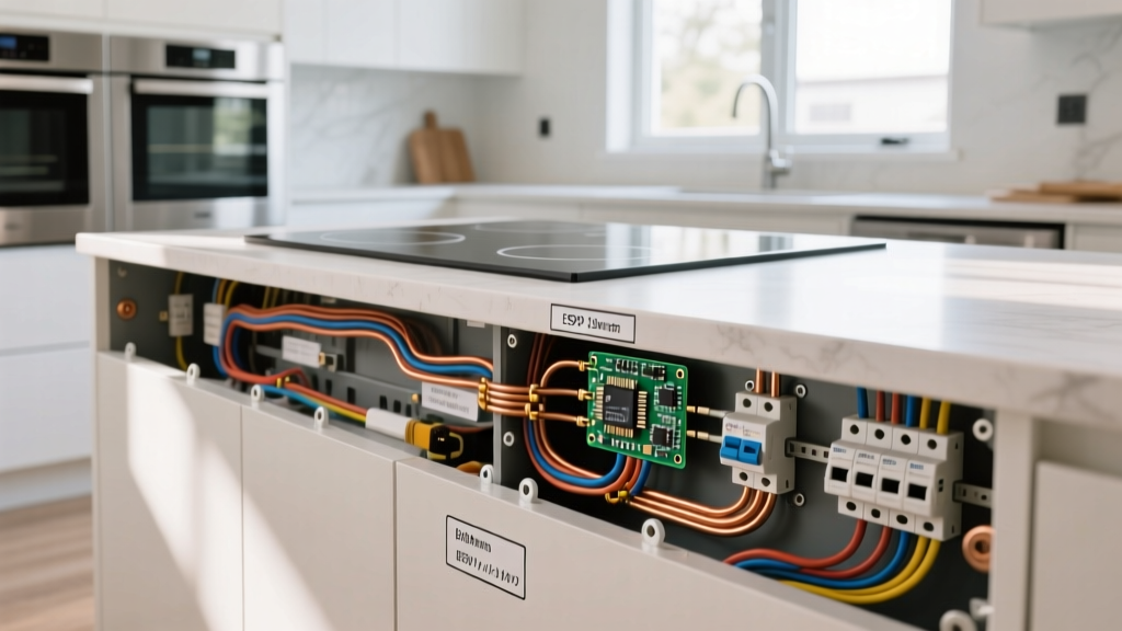

The Shift to Electrification in Modern Kitchen Remodels
Kitchen renovations in 2026 are heavily skewed toward electrification. With local municipalities increasingly banning natural gas in new builds and major remodels, the shift to radiant and induction cooktops is accelerating. According to the U.S. Department of Energy, modern induction hobs offer superior energy efficiency and indoor air quality compared to their gas counterparts. However, swapping a simple 120V gas igniter circuit for a 240V, 40-amp or 50-amp electric hob circuit requires meticulous rough-in planning.
Failing to plan your electric hob wiring before drywall and cabinetry are installed can result in thousands of dollars in retrofitting costs, torn-up subfloors, and delayed project timelines. This guide covers the National Electrical Code (NEC) requirements, cable sizing, and rough-in timelines to ensure your kitchen remodel is safe, compliant, and ready for modern high-draw appliances.
Load Calculations and Breaker Sizing
The first step in renovation planning is understanding the electrical load your new appliance will demand. Induction hobs, such as the popular Bosch 800 Series 36-inch model, can draw up to 9.6kW (9600 watts). Standard 30-inch radiant hobs, like the GE Profile series, typically hover around 7.2kW (7200 watts).
Under NEC Article 220.55, demand factors can be applied to service feeders when calculating the total load of multiple cooking appliances. However, the dedicated branch circuit for a single cooktop must generally be sized to handle the maximum nameplate rating. This prevents nuisance tripping during high-load cooking sessions, such as boiling four pots simultaneously while utilizing the bridge element.
Wire Gauge and Breaker Matrix
Use the following matrix to determine the minimum circuit requirements based on your chosen hob type. Always verify the specific nameplate rating of your exact model before purchasing materials.
| Appliance Type | Typical Wattage | Max Amps (at 240V) | Min. Wire Gauge (Copper) | Breaker Size |
|---|---|---|---|---|
| 30-inch Radiant Hob | 7.2 kW | 30A | 8 AWG (3-conductor) | 40A |
| 36-inch Radiant Hob | 8.4 kW | 35A | 6 AWG (3-conductor) | 40A or 50A |
| 30-inch Induction Hob | 7.4 kW | 31A | 8 AWG (3-conductor) | 40A |
| 36-inch Induction Hob | 9.6 kW | 40A | 6 AWG (3-conductor) | 50A |
Note: While an 8 AWG wire is rated for 40A, a 40A breaker is often used for 30A loads to accommodate continuous use and voltage drop over longer runs. Always defer to the manufacturer's installation manual.
Cable Selection and Routing Compliance
For single-family residential renovations, 6/3 NM-B (commonly known as Romex) is the standard cable for electric hob wiring. The '3' indicates three current-carrying conductors (two hots and one neutral) plus a bare ground.
The Critical Need for a Neutral Wire
A common and costly mistake during kitchen remodels is pulling 6/2 cable instead of 6/3. Many modern induction hobs require a 120/240V connection. The heavy induction coils operate on 240V, but the digital control boards, touchscreens, and internal cooling fans require a 120V circuit, which necessitates a dedicated neutral wire. Failing to provide a neutral will result in a dead appliance and a required re-pull of the wire.
Routing and Stapling Rules
When routing the cable through exposed studs during the rough-in phase, adhere strictly to the National Fire Protection Association (NFPA) NEC guidelines. NM-B cable must be secured by staples or cable ties within 12 inches of the junction box and at intervals not exceeding 4.5 feet. When boring holes through wooden studs, maintain a minimum clearance of 1.25 inches from the edge of the stud to prevent drywall screws from piercing the cable later in the renovation.
The Rough-In Timeline: When to Pull the Wire
Integrating electric hob wiring into your renovation schedule requires precise timing. Here is the ideal sequence for a full kitchen gut-and-remodel:
- Demo and Framing: Remove old cabinets and drywall. Frame any new soffits or islands.
- Electrical Rough-In: Pull the 6/3 NM-B wire from the main service panel (or subpanel) to the designated junction box location. Leave at least 18 inches of slack inside the box.
- Mechanical and Plumbing: Install downdraft ventilation ducting and plumbing lines. Ensure the electrical wire is not pinched by HVAC ducts.
- Insulation and Drywall: Insulate exterior walls and hang drywall. The electrician will 'trim out' the junction box after the drywall is cut.
- Cabinetry Installation: Cabinets are installed, ensuring the junction box remains accessible and is not blocked by drawer boxes.
- Finish and Termination: The hob is dropped into the countertop cutout, and the flexible whip is connected to the junction box.
Junction Box Placement and the Appliance Whip
Unlike freestanding ranges that plug into a NEMA 14-50 receptacle, built-in electric hobs hardwire directly into a junction box using a flexible metal conduit whip (usually provided by the manufacturer).
Proper placement of this junction box is a frequent point of failure in renovation planning. The box should be mounted 12 to 18 inches below the countertop, offset to the left or right side of the cabinet base. Never place the junction box directly under the center of the hob. The center space is often occupied by the hob's internal cooling fans, downdraft ventilation motors, or shallow utensil drawers. If the box is placed in the center, the hob will not sit flush in the countertop cutout, ruining the aesthetic and voiding the warranty.
Use a 4-inch by 4-inch by 2.125-inch metal junction box. Plastic boxes are generally not permitted for hardwired 240V appliance connections in many jurisdictions due to the heat generated and the mechanical stress of the heavy flexible whip.
Gas-to-Electric Retrofitting Edge Cases
Converting a kitchen island from a gas cooktop to an electric induction hob in a home with a concrete slab foundation is one of the most challenging renovation scenarios. Because there is no crawlspace or basement to route the wire beneath the floor, you must find alternative pathways for the heavy 6 AWG cable.
- Core Drilling: Hire a concrete cutting specialist to core drill a 2-inch hole through the slab from the basement or crawlspace below, or trench the slab if no lower level exists.
- Hollow Columns: If the island features a decorative structural column, run the EMT conduit or MC cable up through the hollow center.
- Surface Raceways: As a last resort, use heavy-duty, paintable Wiremold surface raceways routed along the toe-kick of the cabinetry, though this is rarely aesthetically acceptable in high-end 2026 kitchen designs.
Common Renovation Mistakes and Failure Modes
Even experienced DIYers and general contractors can stumble when dealing with high-amperage kitchen circuits. Avoid these critical failure modes:
1. Aluminum Wire Oxidation and Torque Failures
To save on material costs, some electricians use 4 AWG Aluminum SER cable instead of 6 AWG Copper. While legal and safe when installed correctly, aluminum wire expands and contracts differently than copper. If the breaker and junction box terminals are not treated with an anti-oxidant compound (like Noalox) and tightened to the exact inch-pound specification using a calibrated torque screwdriver, the connection will degrade, overheat, and potentially cause a fire.
2. Ignoring AFCI Requirements
Modern electrical codes have evolved significantly. The Electrical Safety Foundation International (ESFI) heavily advocates for arc-fault protection in kitchens. While hardwired appliances sometimes receive exemptions depending on the local Authority Having Jurisdiction (AHJ), many 2026 NEC adoptions require Arc-Fault Circuit Interrupter (AFCI) protection on kitchen branch circuits. Ensure your panel has the physical space for a 2-pole AFCI breaker before finalizing your rough-in plan.
3. Voltage Drop on Long Runs
If your main electrical panel is in the far corner of the basement and the kitchen island is 120 feet away, a standard 6 AWG wire will experience significant voltage drop under a 40A load. This causes the induction hob's internal relays to chatter and the control board to reset unexpectedly. For runs exceeding 100 feet, upsize the wire to 4 AWG copper to maintain a voltage drop of less than 3%.
Safety Warning: Electric hob wiring involves high-voltage, high-amperage circuits that can cause fatal shocks or severe electrical fires if terminated incorrectly. While planning the route and understanding the code is essential for a renovation manager, the physical pulling, stripping, and termination of 240V circuits must be performed by a licensed electrician and inspected by your local building department.
Finalizing Your Renovation Plan
Successful electric hob wiring is entirely about foresight. By calculating the exact load of your chosen appliance, pulling the correct 3-conductor cable, and strategically placing the junction box away from moving parts and ventilation, you ensure your kitchen remodel is both beautiful and functionally flawless. Coordinate closely with your cabinet maker, countertop fabricator, and licensed electrician to ensure the physical dimensions of the hob and the electrical rough-in align perfectly before the first sheet of drywall goes up.


