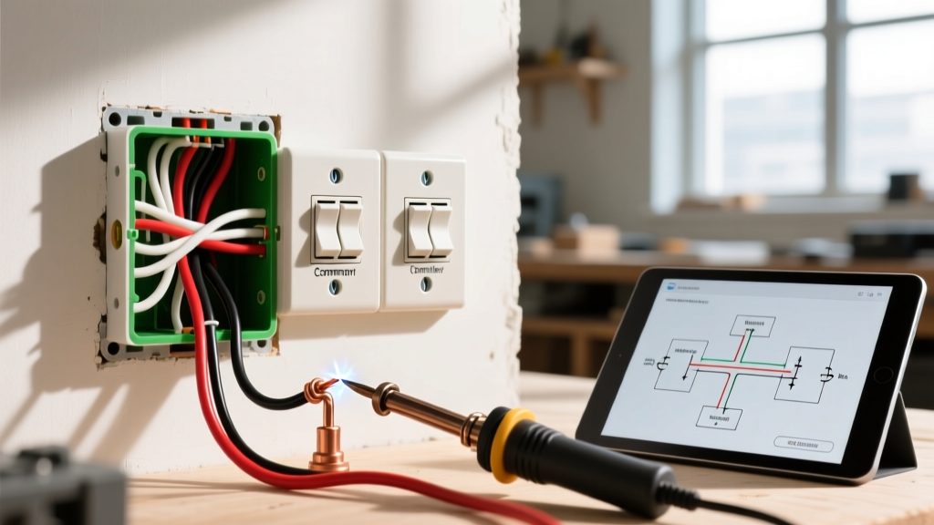

Mastering Basic Electrical Wiring: 3 Way Switch Installation
Controlling a single hallway or staircase light fixture from two separate locations is one of the most practical and highly requested home electrical upgrades. While standard single-pole switches interrupt a single hot wire, mastering basic electrical wiring for a 3 way switch requires understanding a continuous loop utilizing 'traveler' wires. When executed correctly, this setup provides seamless control; when wired poorly, it results in phantom voltages, tripped breakers, or switches that only work in specific toggled positions.
This comprehensive home project guide breaks down the exact anatomy, material costs, and step-by-step execution for a standard 15-amp residential 3-way circuit, adhering to the latest 2023/2026 National Electrical Code (NEC) standards.
Safety First: Always shut off the main breaker for the specific circuit at the service panel before beginning any rough-in or termination work. Verify zero voltage using a non-contact tester and a multimeter. For more on residential electrical safety, refer to the U.S. Consumer Product Safety Commission (CPSC) Electrical Safety Guidelines.
Tools, Materials, and 2026 Pricing
Using commercial-grade components prevents the premature failure associated with builder-grade builder switches. Below is the precise bill of materials for a standard 15-amp hallway run using 14 AWG copper.
| Component | Recommended Model / Spec | Est. Cost (2026) | Purpose |
|---|---|---|---|
| 3-Way Switch (Qty 2) | Leviton Decora 5603-2W (15A, 120V) | $18.50 / pair | Primary switching mechanism with side-clamp terminals |
| Power Feed & Load | Southwire 14/2 NM-B Romex | $0.58 / ft | Carries Line (Hot), Neutral, and Ground to Box 1; Load from Box 2 |
| Traveler Run | Southwire 14/3 NM-B Romex | $0.82 / ft | Carries two Travelers and a Neutral between the two switch boxes |
| Wire Connectors | WAGO 221 Lever Nuts (3-Conductor) | $0.65 / ea | Vibration-proof, reusable splicing for neutrals and grounds |
| Voltage Tester | Klein Tools NCVT-2 (Dual Range) | $27.00 | Verifies 12V to 1000V AC presence before touching terminals |
| Wire Strippers | Klein Tools 11063W (10-22 AWG) | $24.00 | Cleanly strips 14 AWG without nicking the copper core |
Anatomy of a 3-Way Circuit
Unlike a single-pole switch that simply breaks the hot leg, a 3-way switch acts as a directional diverter. The current is routed down one of two possible paths (the travelers) depending on the physical position of the toggle.
Terminal Identification
- Common Terminal (Black/Copper Screw): This is the anchor point. On the 'Line' switch, the constant hot wire connects here. On the 'Load' switch, the wire leading to the light fixture connects here.
- Traveler Terminals (Brass Screws): These two screws accept the traveler wires. They are interchangeable; swapping the red and black traveler wires between the brass screws will not affect the circuit's operation.
- Ground Terminal (Green Screw): Connects to the bare copper equipment grounding conductor.
- Neutral Wires (White): Crucial Code Note: Standard mechanical 3-way switches do not connect to the neutral wire. Neutrals must be spliced together and passed through the switch boxes to the fixture to complete the 120V circuit. (Smart 3-way switches, however, do require a neutral connection).
Step-by-Step Wiring Execution
For this guide, we assume a standard topology: Power enters Switch Box 1, a 14/3 traveler cable runs to Switch Box 2, and a 14/2 load cable runs from Switch Box 2 up to the ceiling fixture.
Step 1: Rough-In and Cable Preparation
- Strip back the outer NM-B sheathing exactly 3/4 of an inch inside the electrical box to prevent exposed bare wires from shorting against the box walls.
- Strip exactly 5/8 of an inch of insulation from the individual 14 AWG conductors. This is the precise depth required for WAGO 221 lever nuts and Leviton side-clamp terminals.
Step 2: Wiring Switch Box 1 (The Line Side)
- The Hot Feed: Connect the incoming black (hot) wire from the 14/2 power feed directly to the Common (Black) screw on Switch 1.
- The Travelers: Take the red and black wires from the 14/3 traveler cable and terminate them on the two Brass screws on Switch 1.
- The Neutrals: Splice the incoming white neutral and the white neutral from the 14/3 cable together using a WAGO lever nut. Add a 6-inch white pigtail if required by local code for box fill or future smart-switch upgrades, but do not connect it to the mechanical switch.
- The Grounds: Splice all bare copper wires (feed, 14/3, and a pigtail to the switch's green screw) together.
Step 3: Wiring Switch Box 2 (The Load Side)
- The Load Leg: Connect the black wire from the 14/2 cable (heading up to the light fixture) to the Common (Black) screw on Switch 2.
- The Travelers: Connect the red and black wires from the incoming 14/3 cable to the two Brass screws on Switch 2.
- The Neutrals: Splice the white wire from the 14/3 cable with the white wire from the 14/2 load cable. This passes the neutral up to the light fixture.
- The Grounds: Bond all bare copper wires and pigtail to the green ground screw.
Step 4: The Ceiling Fixture
At the fixture, you will have a 14/2 load cable arriving from Switch Box 2. Connect the black wire to the fixture's hot lead, the white wire to the fixture's neutral lead, and the bare copper to the fixture canopy ground. According to the NFPA National Electrical Code (NEC), all wire splices inside the canopy must be contained within an approved junction box or listed fixture canopy.
Common Wiring Failure Modes & Troubleshooting
When a DIY 3-way circuit fails, it is almost always due to a misunderstanding of the 'Common' terminal. Use this diagnostic matrix to identify your error without tearing open the drywall.
| Symptom | Probable Cause | Corrective Action |
|---|---|---|
| Light only turns on/off from one switch; the other does nothing. | The Line or Load hot wire was mistakenly wired to a Brass (traveler) screw instead of the Black (common) screw. | Identify the odd-colored screw (Common) on both switches. Ensure the single hot source and single load wire are on these screws. |
| Light works, but only if Switch A is in the 'Up' position. | A traveler wire is broken, disconnected, or miswired, effectively turning the circuit into a single-pole loop. | Check the 14/3 traveler connections at both brass terminals. Ensure the wire insulation isn't pinched under the screw plate. |
| Breaker trips instantly upon flipping a switch. | A hot-to-ground short, or the neutral was mistakenly used as a traveler. | Verify that the white neutral wires are strictly bypassing the switches and only spliced together in the background. |
| Switch faceplate feels warm to the touch after extended use. | Wire insulation was stripped too far, exposing bare copper, or 'backstabbing' push-in connectors were used. | Never use push-in backstabs for 14 AWG solid wire. Wrap the wire clockwise around the side terminal screw or use WAGO lever nuts with pigtails. |
NEC Code Compliance and Best Practices
When performing any basic electrical wiring, adherence to the NEC is non-negotiable for safety and home insurance compliance.
Box Fill Calculations (NEC Article 314.16)
A common mistake in 3-way wiring is overstuffing standard single-gang boxes. A standard 18-cubic-inch single-gang box is usually sufficient for a 3-way switch, but if you are splicing multiple 14/3 and 14/2 cables, you must calculate the box fill. Each 14 AWG conductor counts as 2.0 cubic inches. If your math exceeds the box volume, you must upgrade to a deep single-gang box (22.5 cu in) or a double-gang mud ring.
AFCI Protection Requirements
Under the 2023 and 2026 NEC cycles, Arc-Fault Circuit Interrupter (AFCI) protection is required for virtually all 15-amp and 20-amp branch circuits supplying outlets and devices in residential hallways, bedrooms, and living spaces. Ensure the breaker powering your new 3-way hallway circuit is a Dual-Function (AFCI/GFCI) or standard AFCI breaker, depending on your local jurisdiction's specific adoption amendments.
Final Testing Protocol
Before installing the faceplates and pushing the switches back into the drywall boxes, perform a mechanical and electrical validation:
- Restore power at the main panel.
- Use your Klein NCVT-2 to verify voltage is present at the Line switch's common terminal.
- Toggle Switch 1 and Switch 2 independently in all four possible combinations (Up/Up, Up/Down, Down/Up, Down/Down). The light must toggle on and off seamlessly in every sequence.
- If the light flickers or the switch emits a faint buzzing sound, immediately cut power. Buzzing indicates a loose terminal connection causing micro-arcing, which is a primary precursor to electrical fires.
By utilizing commercial-grade Leviton switches, WAGO lever nuts, and strictly adhering to traveler/common terminal logic, your 3-way switch installation will provide decades of safe, reliable operation.