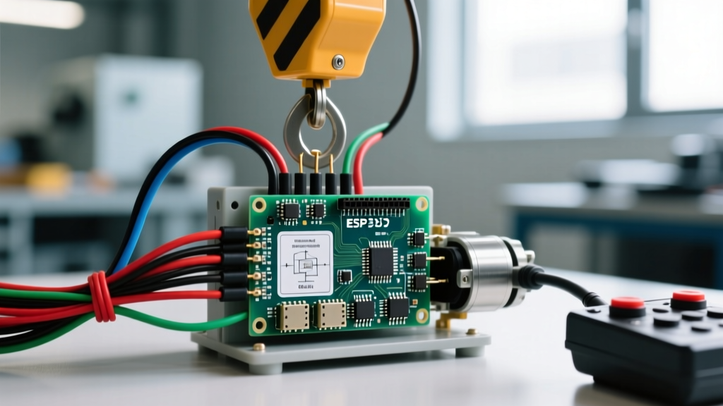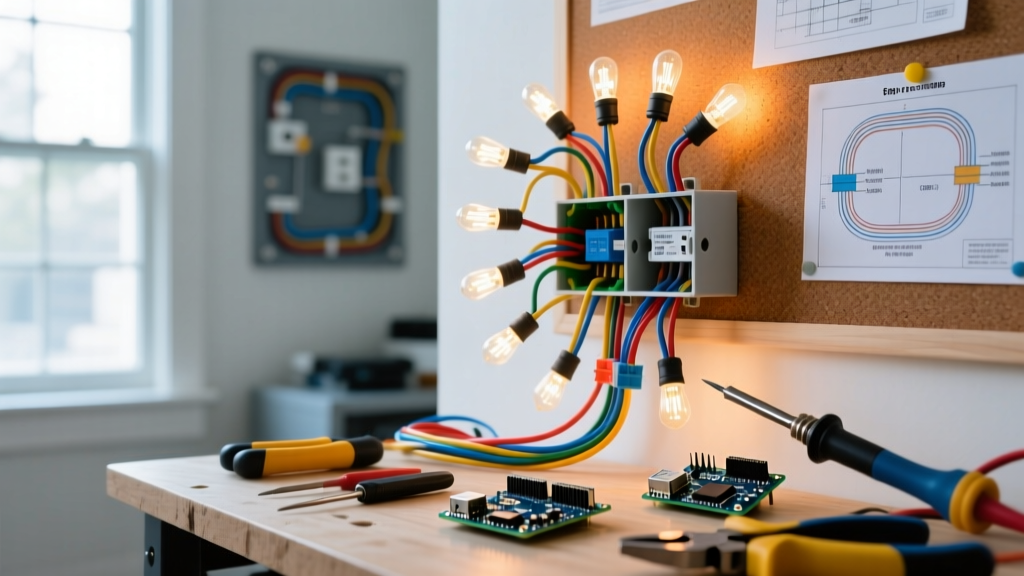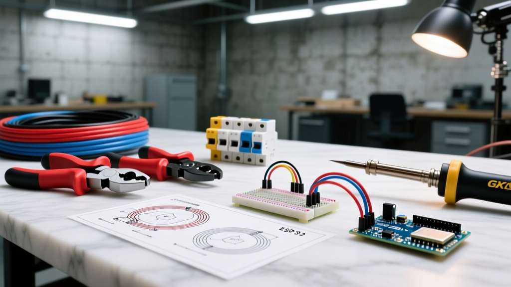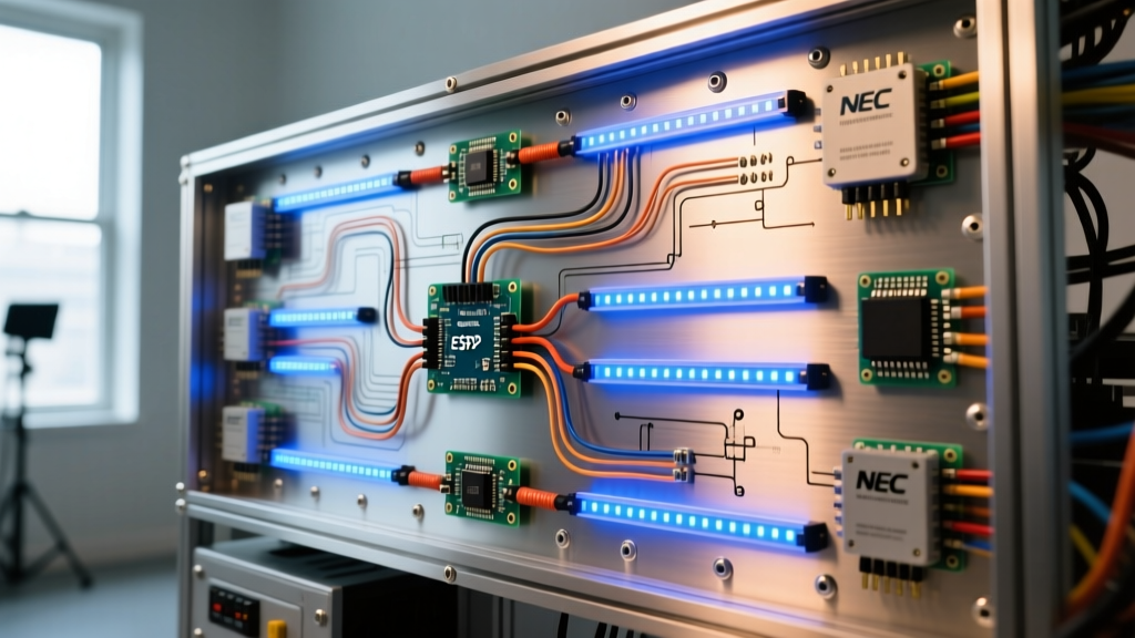

The Commercial Shift: Why Standard LED Arduino Wiring Fails at Scale
Transitioning from a workbench prototype to a permanent commercial installation requires a fundamental rethinking of your approach to LED Arduino wiring. In a hobbyist environment, a few jumper wires and a 5V USB power bank might successfully illuminate a strip of WS2812B addressable LEDs. However, in commercial settings—such as retail signage, interactive architectural facades, or museum exhibits—standard hobbyist wiring topologies inevitably lead to catastrophic failure modes. These include severe voltage drop, data signal degradation due to electromagnetic interference (EMI), and potential fire hazards from undersized conductors.
Commercial electrical contractors and IoT integrators must elevate their LED Arduino wiring strategies to meet industrial reliability standards and strict electrical codes. This guide provides a comprehensive, field-tested framework for scaling Arduino-based LED systems for commercial deployment in 2026, focusing on robust power distribution, signal integrity, and code compliance.
NEC Compliance for Low-Voltage Commercial Installations
Before routing a single data cable, integrators must understand the regulatory landscape governing low-voltage lighting. While Arduino systems operate at safe extra-low voltages (typically 5V to 24V), the power supplies feeding them connect to 120V/240V mains. Furthermore, the National Electrical Code (NEC) has specific mandates for low-voltage lighting systems.
Code Reference: According to the NFPA 70 (National Electrical Code), commercial LED installations often fall under Article 411 (Lighting Systems Operating at 30 Volts or Less) and Article 725 (Class 2 and Class 3 Remote-Control, Signaling, and Power-Limited Circuits). Power supplies must be UL Listed for the specific application, and wiring methods must prevent physical damage and thermal overload.
For commercial LED Arduino wiring, this means you cannot use cheap, uncertified switching power supplies. You must specify UL-listed, Class 2 compliant power sources. Additionally, all 120V/240V AC mains wiring feeding the power supplies must be routed in rigid metal conduit (RMC) or electrical metallic tubing (EMT) by a licensed electrician, maintaining strict physical separation from the low-voltage DC data and power lines to prevent inductive coupling.
Architecture of a Commercial-Grade Arduino LED System
Microcontroller Selection and Industrial I/O
While the classic Arduino Uno is insufficient for large-scale commercial displays, the Arduino Mega 2560 and the industrial-grade Arduino Portenta H7 are mainstays in commercial IoT deployments. The Portenta H7 (retailing around $115 in 2026) features a dual-core STM32H747 processor, offering the computational overhead required for real-time DMX-to-SPI translation and complex generative lighting algorithms without dropping frames.
However, raw GPIO pins on any microcontroller are highly susceptible to electrostatic discharge (ESD) and voltage spikes common in commercial buildings. A critical rule of professional LED Arduino wiring is galvanic isolation. Never connect an Arduino GPIO pin directly to a long run of LED data lines. Instead, use high-speed optocouplers (like the Toshiba TLP281) or digital isolators (like the Texas Instruments ISO7741) on a custom DIN-rail shield to protect the microcontroller from ground loops and transient surges.
Power Distribution and Voltage Drop Mitigation
Addressable LEDs like the SK6812 or WS2812B draw approximately 60mA per pixel at full white brightness. A commercial display with 1,000 pixels will draw 60 Amps at 5V (300 Watts). Relying on a single power injection point is a guaranteed path to failure due to voltage drop across the copper traces of the LED strip and the wiring harness.
Commercial integrators specify industrial power supplies like the Mean Well HLG-600A-5 (5V, 100A, ~$145). The HLG series features a metal enclosure, built-in active PFC (Power Factor Correction), and overload protection, making it ideal for enclosed commercial signage. To manage voltage drop, power must be injected in parallel at regular intervals using a 'star grounding' and 'distributed power' topology.
Wire Gauge vs. Max Run Length for 5V Addressable LEDs
Selecting the correct wire gauge is non-negotiable in commercial LED Arduino wiring. The following table outlines maximum run lengths for 5V systems to maintain a voltage drop of less than 0.25V (ensuring the data line remains above the 0.7 x VDD logic threshold required by the LEDs).
| Wire Gauge (AWG) | Max Current (Amps) | Max Run Length (One Way) | Commercial Application Scenario |
|---|---|---|---|
| 12 AWG | 20A | 12.5 feet (3.8m) | Main trunk from Mean Well PSU to distribution block |
| 14 AWG | 15A | 8.5 feet (2.6m) | Sub-branches to local LED injection nodes |
| 18 AWG | 5A | 4.0 feet (1.2m) | Final pigtail injection directly to LED strip pads |
| 22 AWG | 2A | 2.5 feet (0.75m) | Data line (with twisted ground reference) |
Note: Always calculate voltage drop using the specific resistance of your chosen copper wire. As detailed in the Adafruit NeoPixel Best Practices Guide, exceeding a 0.5V drop on a 5V system will cause the blue and green diodes to brown out first, resulting in severe color shifting across the display array.
Step-by-Step Wiring Protocol for Commercial Displays
To ensure long-term reliability and pass commercial building inspections, follow this rigorous wiring protocol:
- DIN-Rail Enclosure Preparation: Mount the Arduino Portenta/Mega, Mean Well power supply, and terminal blocks inside a NEMA 12 or NEMA 4X rated steel enclosure. Use slotted PVC wiring ducts inside the panel to separate 120V AC mains from 5V DC lines by at least 2 inches.
- Logic Level Shifting: If your Arduino operates at 3.3V logic (or if you are driving 5V WS2812B LEDs from a 5V Arduino but need to boost the signal for noise immunity), route the data pin through a SN74AHCT125N level shifter. This ensures a crisp, high-current 5V logic signal capable of driving the data line without rising-edge degradation.
- Twisted Pair Data Routing: Never run a single, unshielded data wire. Always use a twisted pair (such as Cat6 cable) where one wire carries the data signal and the other carries the signal ground. This creates a localized return path that drastically reduces the loop area, making the data line highly resistant to EMI from nearby commercial HVAC systems or fluorescent ballasts.
- Distributed Power Injection: Solder 18 AWG silicone-jacketed wire to both the VCC and GND pads of the LED strip every 50 pixels (or every 3 amps of draw). Route these back to a central fused distribution block (using 5A automotive blade fuses for each branch) rather than daisy-chaining power through the LED strip's internal PCB traces.
- Signal Termination: For data runs exceeding 3 meters between the Arduino and the first LED pixel, insert a 300-ohm to 500-ohm resistor in series with the data line at the source, and consider a pull-up resistor at the receiving end to prevent floating logic states during microcontroller boot sequences.
Troubleshooting Edge Cases in Commercial Environments
Even with meticulous planning, commercial environments introduce unique electrical noise and physical challenges. Here is how to diagnose and resolve advanced failure modes:
- Random LED Flickering Near HVAC Units: Variable Frequency Drives (VFDs) on commercial air handling units generate massive amounts of high-frequency EMI. If your LEDs flicker randomly when the AC kicks on, your data line is acting as an antenna. Solution: Switch to shielded Cat6a for the data run, ensure the shield is grounded at the Arduino enclosure only (to prevent ground loops), and add a ferrite bead choke near the LED injection point.
- Microcontroller Resets During White-Out Scenes: When the entire LED array transitions to full white simultaneously, the sudden inrush current can cause a momentary voltage sag on the 5V rail, brown-outing the Arduino's onboard voltage regulator. Solution: Isolate the Arduino's power supply from the LED power supply. Use a separate, small 5V 2A buck converter fed directly from the 12V/24V main line, and add a 1000µF electrolytic capacitor across the Arduino's Vin and GND pins.
- Data Signal Degradation Over Long Distances: Standard TTL logic signals cannot reliably travel more than 50cm without degradation in noisy environments. Solution: For runs over 10 meters, abandon direct TTL wiring. Instead, use RS-485 transceiver modules (like the MAX485) at both the Arduino and the LED receiver end, or utilize fiber-optic SPI adapters to guarantee zero EMI interference across commercial floors.
Final Thoughts on Commercial Safety and Maintenance
Professionalizing your LED Arduino wiring is about shifting from a mindset of 'making it work' to 'ensuring it never fails.' By adhering to OSHA's general requirements for electrical equipment safety, utilizing industrial-grade power supplies, implementing galvanic isolation, and respecting the physics of voltage drop, you can deploy Arduino-driven LED installations that rival the reliability of hardwired DMX architectural lighting. Always document your wiring schematics, label every fused branch, and provide facility managers with a clear maintenance schedule for inspecting terminal block torque and thermal imaging of power distribution nodes.