
The Inspector's Lens: Why 3-Way Switches Fail Inspection
When it comes to residential and commercial lighting control, the electrical wiring 3 way switch configuration is ubiquitous. Allowing control of a single lighting load from two distinct locations, 3-way switches utilize Single-Pole Double-Throw (SPDT) mechanics. However, from an Authority Having Jurisdiction (AHJ) perspective, these circuits are notorious for code violations. The complexity of routing travelers, managing neutral conductors, and calculating box fill volumes creates multiple opportunities for errors.
As we navigate the 2026 construction landscape, electrical inspectors are increasingly strict about smart-home readiness and LED compatibility. Mastering the electrical wiring 3 way switch layout requires more than just making the lights turn on; it demands strict adherence to the National Electrical Code (NEC). According to the NFPA 70 National Electrical Code, improper switch wiring remains a leading cause of failed residential rough-in and final inspections.
NEC 404.2(C): The Neutral Conductor Mandate
Historically, electricians routed a 2-wire cable to a 3-way switch location, using the white and black wires as travelers, and relying on the fixture box for the neutral. This practice is now a guaranteed inspection failure. NEC Article 404.2(C) mandates that a grounded circuit conductor (neutral) must be provided at nearly all switch locations controlling lighting loads.
Why the AHJ Cares About the Neutral
The proliferation of smart switches, timers, and occupancy sensors requires a continuous 120V standby circuit. Devices like the Lutron Maestro (MACL-153M) or the Leviton Decora Smart (D2S3S) require a neutral connection to power their internal Wi-Fi radios and LED indicators without causing ghost-voltage leakage through the lighting load. If an inspector opens a 3-way switch box and finds no white neutral wire capped and tucked in the back, they will red-tag the installation.
Expert Insight: Always run 14/3 or 12/3 NM-B cable from the line source to the first 3-way switch to ensure the neutral is present. If you are remodeling an older home where pulling a new 3-wire cable is structurally impossible, you must document the exception under NEC 404.2(C)(1) and use a wireless smart switch system (like Lutron Caseta) that does not require a neutral at the secondary switch location.
Box Fill Calculations: The Silent 3-Way Violation
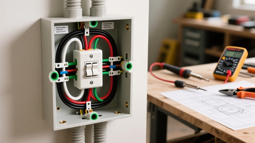
The most common reason a perfectly functional 3-way switch fails inspection is box fill violation under NEC Article 314.16. Inspectors do not just count wires; they count volume allowances. A standard single-gang 'old work' plastic box typically offers 14 to 18 cubic inches of space. A 3-way switch box often acts as a junction point, easily exceeding this limit.
The Math Behind the Violation
Let us calculate a standard 3-way switch box where power enters, and two traveler cables exit to the second switch and the light fixture. We will use 14 AWG wire, which requires 2.0 cubic inches per volume allowance.
| Component | Count | Volume Allowance (14 AWG) | Total Cu In |
|---|---|---|---|
| Hot, Neutral, Travelers (Entering/Leaving) | 7 Conductors | 1 per conductor | 14.0 |
| Equipment Grounding Wires | 1 Allowance (All grounds) | 1 | 2.0 |
| Internal Cable Clamps | 1 Allowance | 1 | 2.0 |
| Switch Yoke (Device) | 2 Allowances | 2 | 4.0 |
| Total Required Volume | - | - | 22.0 Cu In |
As the matrix above demonstrates, you need a minimum of 22.0 cubic inches. A standard 18 cu in single-gang box is a direct NEC violation. To pass inspection, you must upgrade to a deep single-gang box (such as the Carlon E982AR-UPC 22.5 cu in extra-deep box) or use a 4-inch square metal box with a single-gang plaster ring.
Traveler Re-Identification: NEC 200.7 Compliance
When planning your electrical wiring 3 way switch project, you will inevitably use the white wire in a 14/3 or 12/3 Romex cable as a traveler or a switched hot. The NEC strictly prohibits using a white or gray wire as an ungrounded (hot) conductor without permanent re-identification.
Inspectors look for black or red electrical tape wrapped completely around the insulation at both the termination point and the sheath entry. Using a black Sharpie marker is widely rejected by AHJs as it fades and is not considered 'permanent.' Furthermore, the re-identification must encircle the wire; a single stripe down the side is a code violation. If an inspector sees a bare white wire connected to the brass traveler screw of a 3-way switch, the circuit will fail immediately.
Grounding and Bonding: Metal vs. Non-Metallic Boxes
Grounding rules shift depending on the enclosure material, and inspectors verify this meticulously during the rough-in phase.
- Non-Metallic (Plastic) Boxes: The equipment grounding conductor (EGC) must be connected directly to the green grounding screw on the 3-way switch. The box itself requires no bonding.
- Metal Boxes: The EGC must first be bonded to the metal box using a green grounding screw or a grounding clip. A pigtail must then be run from the box (or from the wire nut splice) to the switch's green screw. Relying solely on the metal mounting screws of the switch yoke to ground the device is a violation of NEC 404.9(B) unless specific conditions (like self-grounding clips on the yoke making direct metal-to-metal contact) are met. Best practice for 2026 compliance is to always run a dedicated ground pigtail to the switch.
Common 3-Way Inspection Red Flags Matrix
The International Association of Electrical Inspectors (IAEI) frequently highlights recurring field violations. Below is a troubleshooting matrix for common 3-way switch failures.
| Failure Mode | NEC Violation | Required Correction |
|---|---|---|
| Switch loop using 14/2 (no neutral at switch) | 404.2(C) | Replace with 14/3 NM-B to provide grounded neutral. |
| White wire used as traveler without tape | 200.7(C) | Apply black PVC electrical tape at both ends of the run. |
| Wires stripped too far, exposing bare copper outside terminal | 110.14 / 300.15 | Trim wires; insulation must butt up against the terminal plate. |
| Push-in (backstab) connections used on 15A/20A circuits | 110.14 (Workmanship) | Use side-wire terminal screws or UL-listed push-in connectors rated for the specific wire gauge. |
Pre-Inspection Checklist for Electricians
Before calling the AHJ for a final inspection, run through this physical verification checklist to ensure your electrical wiring 3 way switch installation is bulletproof:
- Yoke Alignment: Ensure the switch yoke is flush with the wall plate. Gaps exceeding 1/8th of an inch violate NEC 404.9(A).
- Wire Dressing: Neatly fold the wires into the back of the box. Inspectors check for 'bird-nesting' which damages insulation and creates heat pockets.
- Sheath Entry: Verify the NM-B cable jacket extends at least 1/4 inch inside the box past the cable clamp.
- Terminal Torque: While residential inspectors rarely use torque screwdrivers on standard 15A switches, ensuring screws are tightened to the manufacturer's spec (usually 12-14 in-lbs) prevents arcing and thermal imaging failures during advanced commercial inspections.
For ongoing updates on code interpretations and field inspection standards, resources like Electrical Contractor Magazine (ECM) Codes & Standards provide invaluable, up-to-date analysis of how local jurisdictions are enforcing the latest NEC revisions. By prioritizing box fill, neutral availability, and precise traveler identification, your 3-way switch installations will pass inspection on the first visit, every time.