
The 'Series' Myth: Physics, Code, and Residential Wiring
Search any DIY forum for advice on adding a new receptacle to an existing wall, and you will inevitably encounter the phrase wiring electrical outlets in series. From a strict electrical engineering and National Electrical Code (NEC) perspective, this terminology is fundamentally flawed and describes a physical configuration that is both non-functional for standard appliances and highly dangerous.
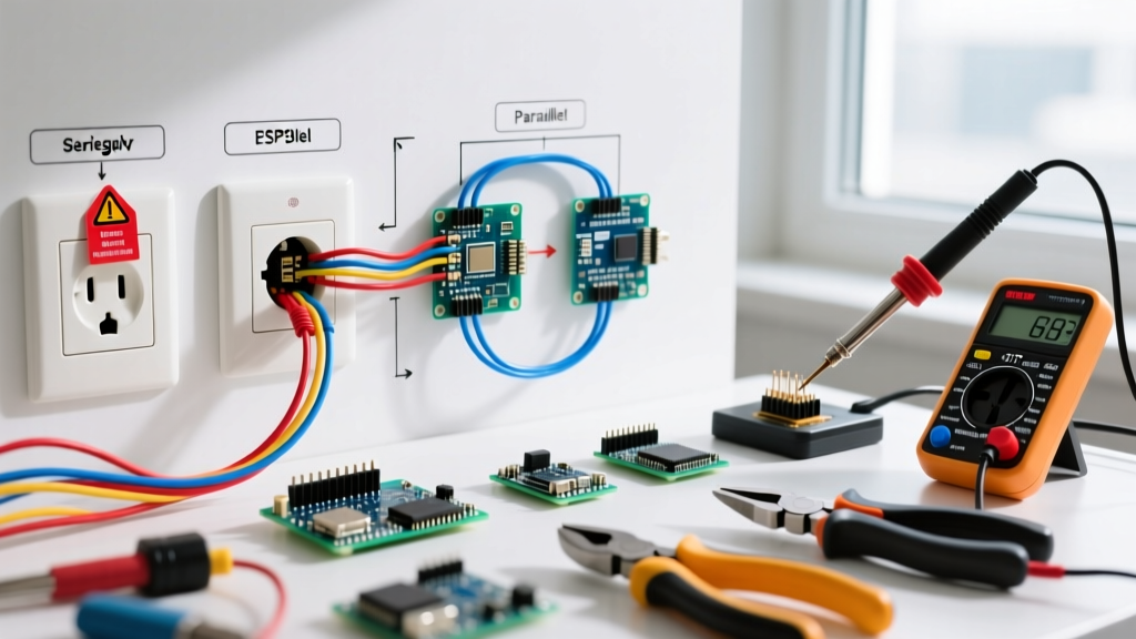
In residential and commercial alternating current (AC) power distribution, branch circuits must be wired in parallel. Wiring 120V receptacles in a true electrical series—where the current must pass through the first load to reach the second—would result in catastrophic voltage drop. If you wired a 120V television and a 120V lamp in series, each device would receive roughly 60V, failing to operate and potentially damaging internal power supplies.
What DIYers and even some apprentice electricians colloquially call 'series wiring' is actually daisy-chaining (parallel wiring utilizing the receptacle's internal yoke as a junction point). While daisy-chaining is a valid parallel wiring method under specific conditions, the NEC places strict limitations on how conductors are spliced, terminated, and maintained to ensure safety and continuity. This guide breaks down the code-compliant realities of chaining outlets, the dangers of true series wiring, and the exact standards inspectors enforce in 2026.
True Series vs. Parallel Branch Circuits
To understand why the NEC mandates parallel wiring for receptacles, we must look at the physics of the circuit. According to OSHA electrical safety guidelines and foundational circuit theory, branch circuits are designed to deliver a constant voltage (120V or 240V) to multiple independent loads simultaneously.
The Series Failure Mode
In a true series circuit, the total resistance is the sum of all individual load resistances. The current is constant, but the voltage divides among the loads. If one device is unplugged or a filament breaks, the entire circuit opens, and all downstream devices lose power—much like vintage Christmas tree lights. This violates the core requirement of a branch circuit, which must allow independent operation of plugged-in equipment.
The Parallel Standard
In a parallel circuit, the voltage across each receptacle remains a constant 120V. The total current drawn is the sum of the currents drawn by each individual device. The NEC National Electrical Code (NFPA 70) Article 210 governs branch circuits, implicitly requiring parallel configurations to ensure that the removal or failure of one receptacle does not interrupt the ungrounded (hot) conductor to downstream devices.
Daisy-Chaining: What DIYers Mean by 'Series'
When an electrician runs a 14/2 or 12/2 NM-B (Romex) cable from the panel to the first outlet, and then runs another cable from the first outlet to the second, they are wiring in parallel. The incoming wires connect to the LINE terminals, and the outgoing wires connect to the LOAD terminals on the duplex receptacle (such as the Leviton T5262 15A tamper-resistant duplex).
While this is parallel wiring, it relies on the receptacle's internal metal yoke and terminal screws to carry the full circuit current to the next device. This introduces specific code vulnerabilities, particularly regarding the neutral conductor.
Pigtailing vs. Daisy-Chaining: A Code Comparison Matrix
Modern electrical best practices and strict local code adoptions heavily favor pigtailing over daisy-chaining through receptacle terminals. Pigtailing involves joining all incoming, outgoing, and receptacle wires together in the back of the electrical box using a wire connector, effectively removing the receptacle from the circuit's continuous path.
| Feature | Daisy-Chaining (LINE/LOAD Terminals) | Pigtailing (Wire Nuts / WAGO Lever Nuts) |
|---|---|---|
| Wiring Method | Wires terminate directly on receptacle screws; internal yoke bridges downstream. | Wires spliced in-box; single pigtail connects to receptacle. |
| Neutral Continuity | High Risk. Removing receptacle breaks downstream neutral. | Code Compliant. Neutral remains intact if receptacle is removed. |
| Box Fill Volume | Lower. Fewer wire splices count toward NEC 314.16 fill calculations. | Higher. Wire connectors and pigtails add to box fill volume. |
| Troubleshooting | Difficult. A loose terminal kills downstream power. | Easy. Receptacle issues are isolated to a single device. |
| Material Cost (per box) | $0.00 (uses receptacle terminals) | ~$0.75 (WAGO 221-413 lever nuts + 12 AWG THHN pigtails) |
| Inspection Preference | Accepted for hot/ground, heavily scrutinized or banned for neutrals. | Universal gold standard for 2026 residential inspections. |
Critical NEC Violations to Avoid When Chaining Outlets
If you choose to daisy-chain outlets using the LINE and LOAD terminals, you must navigate several strict NEC articles. Ignorance of these rules is a primary cause of failed rough-in and final inspections.
1. The Neutral Continuity Rule (NEC 300.13(B))
NEC Section 300.13(B) explicitly states that the continuity of a grounded (neutral) conductor shall not depend on a device such as a receptacle or lampholder. Exception: The removal of the device shall not interrupt the continuity.
Code Reality Check: If you daisy-chain the white neutral wire through the silver terminals of a standard receptacle, removing that receptacle to paint the wall or replace it will sever the neutral path for all downstream outlets. On a Multiwire Branch Circuit (MWBC), an open neutral can cause 240V to surge through downstream 120V appliances, instantly destroying electronics and creating a severe fire hazard. Always pigtail the neutral conductor.
2. Box Fill Calculations (NEC 314.16)
When daisy-chaining, you are pulling two cables (4 current-carrying conductors, 2 grounds) into a single box. While you save space by omitting wire nuts, you must still calculate box fill. A standard 18-cubic-inch single-gang nail-on box is generally sufficient for two 14/2 or 12/2 cables and a receptacle, but adding a third cable (chaining three ways) will almost certainly violate box fill limits, requiring a deeper 22-cubic-inch or 4x4 square box.
3. GFCI and AFCI Load-Side Wiring
Many DIYers mistakenly believe that wiring standard outlets to the LOAD terminals of a GFCI receptacle is 'series' wiring. It is actually parallel downstream protection. However, NEC 2023 and 2026 updates require stringent attention to the line/load identification. Reversing the line and load on a GFCI (e.g., Leviton GFNT1-W) will result in the receptacle functioning locally but failing to provide ground-fault protection to downstream devices—a massive code violation and safety hazard.
Step-by-Step: Code-Compliant Parallel Wiring (Pigtail Method)
To achieve the highest standard of safety and ensure your work passes inspection in any jurisdiction, use the pigtail method with modern push-in lever connectors.
- Prepare the Conductors: Strip exactly 3/4 inch of insulation from your 12 AWG or 14 AWG solid copper conductors using a precision wire stripper (e.g., Klein Tools 11063W). Do not nick the copper, which creates a failure point.
- Create the Pigtails: Cut 6-inch lengths of matching THHN/THWN stranded or solid wire (black for hot, white for neutral, bare/green for ground).
- Splice the Neutrals: Insert all incoming white wires, outgoing white wires, and the white pigtail into a WAGO 221-413 3-port lever nut. Close the levers. Tug each wire to verify the clamp engagement.
- Splice the Hots and Grounds: Repeat the process for the black (hot) and bare (ground) conductors. Note: For metal boxes, the ground must also pigtail to the box's internal grounding screw.
- Terminate at the Receptacle: Connect the single black pigtail to the brass LINE screw, the single white pigtail to the silver LINE screw, and the single ground pigtail to the green grounding screw.
- Torque to Specification: This is the most frequently missed step in residential wiring.
Torque Requirements and 2026 Inspection Standards
Since the 2017 NEC cycle, and heavily enforced in 2023 and 2026 adoptions, NEC 110.14(D) requires that all electrical connections be tightened to the manufacturer's specified torque using a calibrated torque tool.
You can no longer simply 'tighten the screw until it feels snug.' For a standard 15A or 20A duplex receptacle, the manufacturer (like Hubbell or Leviton) typically specifies a torque value between 12 in-lbs and 14 in-lbs for 14 AWG and 12 AWG wire. Using an inch-pound torque screwdriver (such as the Klein Tools 32308) prevents two major failure modes:
- Under-torquing: Leads to loose connections, high resistance, arcing, and eventual thermal meltdown of the receptacle face.
- Over-torquing: Strips the brass screw threads or crushes the copper wire, reducing its cross-sectional area and creating a localized hot spot under heavy load (e.g., running a 1500W space heater).
Frequently Asked Questions
Can I wire outdoor landscape lighting in series?
Low-voltage DC landscape lighting (12V or 24V) is sometimes wired in series for specific constant-current LED drivers, but standard 120V AC outdoor receptacles and hardwired fixtures must always be wired in parallel to maintain consistent voltage and comply with NEC Article 225 (Outside Branch Circuits and Feeders).
Does daisy-chaining outlets cause voltage drop?
In a properly sized parallel circuit (e.g., 12 AWG wire on a 20A breaker), the voltage drop across the receptacle terminals is negligible. However, if you daisy-chain more than four or five outlets on a long run (over 75 feet from the panel), you must calculate voltage drop per NEC informational note 210.19(A). Pigtailing reduces the cumulative resistance of the connections, marginally improving voltage stability at the furthest receptacle.
Why do some electricians still use backstab terminals?
Push-in 'backstab' terminals on the rear of 15A receptacles are technically code-compliant for 14 AWG solid wire only. However, they rely on a small internal spring steel wedge that is notorious for loosening under thermal cycling. Master electricians universally avoid them in favor of side-wire terminal screws or rear screw-clamp plates, ensuring a robust, high-surface-area mechanical connection that will not degrade over decades of use.