
The Regulatory Reality: NEC vs. SAE Standards
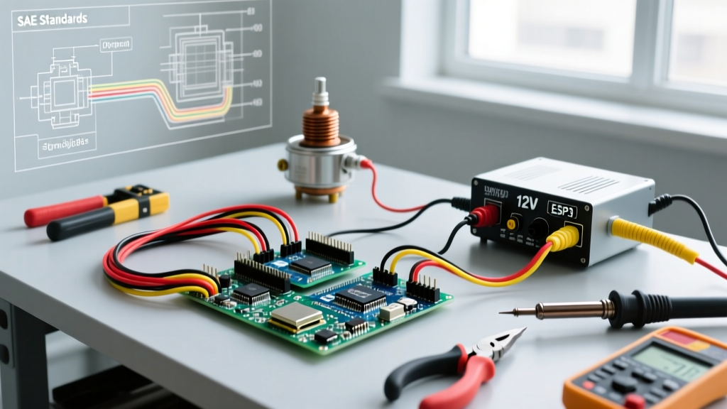
When DIYers and restoration enthusiasts tackle under-hood electrical projects, a common misconception is that the National Electrical Code (NEC) dictates how wires must be routed and fused. However, NFPA 70 Article 90.1(B) explicitly states that the NEC does not cover installations in ships, watercraft, railway rolling stock, aircraft, or automotive vehicles. Therefore, when you are wiring an electric choke on a classic car, tractor, or stationary generator, the governing 'codes' are actually established by the Society of Automotive Engineers (SAE) for land vehicles, and the American Boat and Yacht Council (ABYC) for marine applications.
Electric chokes, which replaced older exhaust-heat and coolant-heat bi-metallic springs on carburetors like the Holley 4160, Edelbrock 1406, and Rochester Quadrajet, rely on a sealed PTC (Positive Temperature Coefficient) heating element. This element heats a bi-metallic spring to gradually open the choke plate as the engine runs. Because this component operates in a high-vibration, high-temperature, and chemically harsh environment, applying standard residential wiring practices is not just incorrect—it is a severe fire hazard. This guide breaks down the exact SAE and ABYC standards required to safely wire a 12V DC electric choke circuit.
Wire Insulation and Gauge: Why PVC Fails Under the Hood
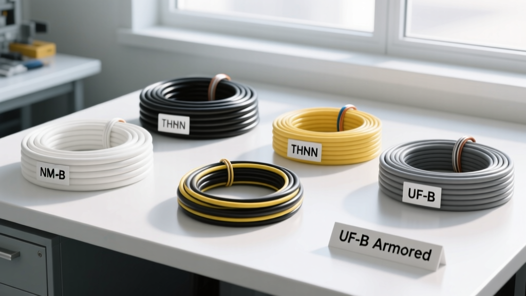
The most frequent failure mode in aftermarket choke wiring is the use of standard hardware-store wire. THHN or THWN wire utilizes PVC (polyvinyl chloride) insulation. Under-hood temperatures near exhaust manifolds and carburetor spacers routinely exceed 100°C (212°F). PVC insulation becomes brittle, cracks, and eventually melts at these temperatures, exposing bare copper to the metal firewall or intake manifold, resulting in a dead short and potential engine bay fire.
To comply with SAE J1128 (Low Tension Primary Cable) standards, you must use wire with XLPE (cross-linked polyethylene) insulation. The two most common variants are GXL and TXL.
Wire Selection Matrix for Electric Chokes
| Wire Type | Insulation Material | Max Temp Rating | Wall Thickness | Recommended Application |
|---|---|---|---|---|
| GXL | XLPE | 155°C (311°F) | Standard | Primary under-hood routing, high-heat zones |
| TXL | XLPE | 125°C (257°F) | Thin | Tight space routing, loom wrapping |
| THHN (Hardware) | PVC / Nylon | 90°C (194°F) | Thick | NEVER use in automotive under-hood |
While the heating element in a standard Holley or Edelbrock electric choke cap only draws between 2.5 and 4.5 amps (meaning an 18 AWG wire could technically carry the load), SAE best practices and ABYC E-11 standards recommend a minimum of 16 AWG SAE wire for mechanical robustness. 14 AWG SAE GXL is the industry gold standard for this circuit, providing excellent voltage drop mitigation over longer runs from the firewall to the carburetor.
Power Source Selection: The 12V DC vs. AC Stator Dilemma
Selecting the correct power source is where most DIY wiring jobs fail. The electric choke requires a switched 12V DC source that is only energized when the ignition key is in the 'Run' position. It must receive full system voltage (13.5V to 14.4V when the alternator is charging) to heat the bi-metallic spring at the correct rate.
Critical Warning: Never wire an aftermarket 12V DC electric choke to the negative terminal of an ignition coil (on points-style systems) or to a ballast resistor bypass wire. These circuits often operate at a reduced 7V to 9V. Supplying under-voltage to the choke cap will cause the spring to heat too slowly, leaving the choke plate partially closed during warm-up, resulting in a rich stumble, fouled spark plugs, and washed cylinder walls.
Identifying Legacy AC Stator Systems
If you are restoring a mid-1970s to 1980s Ford or Chrysler vehicle, the factory choke may have been wired to the alternator's 'Stator' (STA) terminal. This terminal outputs an unrectified AC voltage (typically 7V to 9V AC) that is only present when the engine is physically spinning. If you connect a modern 12V DC aftermarket choke cap to an AC stator tap, the alternating current will rapidly degrade the DC heating element, and the choke will fail to open. Always verify your power source with a multimeter: it should read 0V when the key is off, and 12V+ DC when the key is in the 'Run' position (engine off).
Overcurrent Protection and Fusing Protocols
Both SAE and ABYC standards mandate that overcurrent protection (fusing) be installed as close to the power source as possible. For marine generators equipped with electric chokes, ABYC E-11 requires the fuse to be within 7 inches of the battery or bus bar connection. For automotive applications, placing an inline fuse within 6 to 12 inches of the ignition switch or fuse box tap is the accepted standard.
- Fuse Type: Use a standard ATO/ATC blade fuse holder.
- Fuse Rating: A 5-Amp fuse is ideal. The choke draws ~3 amps, so a 5A fuse provides a safe buffer for inrush current while protecting the 14 AWG wire from melting in the event of a dead short.
- Connector Standard: Use SAE J554 compliant crimp terminals. Avoid soldering under-hood connections, as the heat from the engine can soften the solder, and vibration will cause the rigid solder joint to fatigue and snap the wire.
Step-by-Step Wiring Procedure for 12V DC Electric Chokes
- Locate a Switched 12V Source: Use a multimeter to find a circuit on your fuse box that reads 12V only when the key is turned to 'Run'. An accessory fuse or a dedicated ignition-run fuse is ideal. Use an add-a-circuit fuse tap to maintain factory circuit integrity.
- Install the Inline Fuse: Crimp your 5A inline ATO fuse holder to the power source wire within 7 inches of the connection point.
- Route the Wire: Run the 14 AWG SAE GXL wire through the firewall or along the fender well. Maintain a minimum clearance of 9 inches from exhaust manifolds, headers, and sharp metal edges. Use split-loom tubing or Tesa tape where the wire passes through the firewall or near moving linkages.
- Terminate at the Choke Cap: Crimp a high-quality, heat-shrink sealed ring terminal or spade connector (depending on your carburetor model) to the end of the wire.
- Establish the Ground: This varies by manufacturer. Holley electric choke caps typically ground through the metal base of the cap into the carburetor body (divorced ground). Ensure the mating surface is bare, clean metal. Edelbrock (Carter AFB) caps often feature a dedicated ground spade terminal; run a separate 14 AWG ground wire from this terminal directly to a clean, unpainted bolt on the intake manifold or engine block.
Edge Cases and Real-World Failure Modes
Even when wired to code, electric chokes can exhibit behavioral issues if the physical adjustment or voltage delivery is flawed. Here are the most common edge cases encountered in the field:
1. Voltage Drop Across Corroded Grounds
If your choke takes longer than 4 to 5 minutes to fully open in 70°F ambient weather, you likely have a voltage drop issue. Because Holley caps rely on the carburetor body for a ground, any corrosion, paint, or carburetor base gasket sealer interfering with the cap-to-body contact will increase resistance. Perform a voltage drop test: place your multimeter's positive probe on the choke cap's 12V input terminal and the negative probe directly on the engine block. With the engine running, you should read no more than 0.2V drop across the ground path. If it reads higher, scrape the metal contact points clean.
2. The 'Alternator Excitation' Trap
Some older GM alternators (10SI and 12SI models) require a switched 12V signal to the 'Exciter' (terminal 1) to begin charging. DIYers often splice the electric choke wire into this exciter wire. This is a critical error. The exciter wire passes through a dashboard indicator bulb, which limits the current. The choke will starve the alternator of excitation current, causing the battery to drain, or the choke will receive insufficient amperage to heat the spring. Always use a dedicated, fused circuit for the choke.
3. Cap Indexing and Spring Tension
Wiring the choke perfectly means nothing if the bi-metallic spring is not indexed correctly into the choke lever. When installing the cap, rotate it until the choke plate just barely touches the closed position at ambient cold temperatures, then tighten the retaining screws. If the spring is over-tensioned, the 4-amp heating element will not generate enough rotational force to overcome the spring tension, leaving the engine choked and flooding the cylinders with raw fuel.
By adhering strictly to SAE J1128 wire specifications, utilizing proper 5A overcurrent protection, and ensuring clean, low-resistance grounding paths, you guarantee that your electric choke operates safely and reliably, eliminating cold-start drivability issues without introducing electrical fire risks into the engine bay.