
The Reality of Above Ground Pool Electrical Safety
Setting up an above ground pool is a hallmark summer project, but the transition from assembling the frame to powering the filtration system is where DIYers often make critical, life-threatening errors. According to the U.S. Consumer Product Safety Commission (CPSC), improper grounding and lack of GFCI protection remain leading causes of pool-related electrocutions. In 2026, with the adoption of stricter local amendments to the National Electrical Code (NEC), the margin for error in electrical wiring for above ground pool setups is effectively zero.
This guide bypasses generic advice and provides a granular, code-compliant roadmap for wiring a standard 1.5 HP to 2.0 HP hardwired pool pump, including the often-misunderstood equipotential bonding grid. We will cover exact trenching depths, wire gauges, and specific breaker models required for a safe installation.
2026 NEC Code Requirements for Storable Pools
Under NEC Article 680, above ground pools are classified as "storable pools" (typically defined as having a maximum depth of 42 inches, though many modern resin-hybrid pools exceed this and are treated as permanently installed). Regardless of the exact classification, the electrical safety mandates are stringent.
Critical Code Mandate: All 120V and 240V pool pump motors must be protected by a Ground Fault Circuit Interrupter (GFCI). Standard breakers will not suffice. Furthermore, all outdoor receptacles within 20 feet of the pool's inside wall must also be GFCI-protected and equipped with weatherproof "in-use" covers.
The National Fire Protection Association (NFPA) emphasizes that equipotential bonding is distinct from equipment grounding. While grounding provides a path for fault current to trip the breaker, bonding eliminates voltage gradients between metallic components, preventing a shock hazard if a person simultaneously touches the pool wall and the pump motor.
Material & Cost Matrix for a 1.5 HP Pump Setup
Before digging, you must procure the correct materials. Using direct-burial UF cable is technically permissible but highly discouraged for pool circuits due to the difficulty of future upgrades and physical vulnerability. Rigid PVC conduit with individual THWN-2 conductors is the professional standard.
| Component | Specification / Model Example | Estimated 2026 Cost |
|---|---|---|
| GFCI Breaker (2-Pole, 240V) | Siemens 50A Type A GFCI (Q250GFI) or Eaton BR250GFI | $85 - $110 |
| Conductors (Inside Conduit) | 10 AWG THWN-2 Copper (Black, Red, White, Green) | $1.20 - $1.50 / ft |
| Underground Conduit | 3/4" Schedule 40 PVC (18" trench depth) | $2.50 / 10ft stick |
| Above-Ground Sweep | 3/4" Schedule 80 PVC (Physical damage protection) | $4.00 / 10ft stick |
| Bonding Wire | #8 AWG Solid Bare Copper | $1.80 / ft |
| Pool Timer (Smart/Wi-Fi) | Pentair IntellConnect or Intermatic PE153 | $140 - $220 |
| Bonding Lugs | Intermatic PA100 or Pentair 520269 (Potting compound) | $15 - $25 each |
Total Material Cost Estimate: $350 - $550 depending on the distance from the main electrical panel to the pool equipment pad.
Phase 1: Trenching and Conduit Routing
The physical routing of your circuit dictates the longevity of the installation. Soil shifting, landscaping tools, and root growth can easily compromise shallow wiring.
- Dig to 18 Inches: For Schedule 40 PVC conduit housing THWN-2 wires, the NEC mandates a minimum cover depth of 18 inches. If you opt for Schedule 80 PVC, you can reduce this to 12 inches, but 18 inches is the safest bet against future aeration or planting.
- Bed the Trench: Do not lay PVC directly on rocky soil. Pour a 2-inch bed of play sand or stone dust at the bottom of the trench to prevent point-loads from cracking the conduit over time.
- Install Warning Tape: Lay bright yellow "Caution: Buried Electric Line Below" tape exactly 12 inches above the conduit. This provides a visual warning for anyone digging in the future before their shovel strikes the PVC.
- Use Sweeps, Not 90-Degree Elbows: When transitioning from underground to above ground, use long-sweep PVC fittings. Sharp 90-degree elbows create friction points that make pulling 10 AWG THWN-2 wire nearly impossible without damaging the wire insulation.
- Transition to Schedule 80: Any conduit exposed above ground (from the trench exit up to the pump and timer) must be Schedule 80 PVC to withstand UV degradation and physical impact from weed whackers or lawn equipment.
Phase 2: Equipotential Bonding (The Most Critical Step)
If you skip this step, your installation will fail inspection and, more importantly, poses a severe shock risk. Bonding connects all conductive metal parts together so they share the same electrical potential.
What Must Be Bonded?
- The Pool Wall: If your above ground pool has a metal wall (steel or aluminum), it must be bonded. Use a #8 AWG solid bare copper wire attached via a listed bonding lug (like the Intermatic PA100) secured with a stainless steel screw to prevent rust.
- The Pump Motor Housing: Locate the external bonding lug on the back of your pool pump motor (usually a small brass or copper stud). Attach the #8 AWG wire here.
- Metal Parts Within 5 Feet: Any metal handrails, ladders, diving boards, or metal fences within 60 inches of the pool's inside wall must be integrated into the bonding grid.
- The Water Itself: Modern NEC codes require the water to be bonded. If your pool lacks a metallic underwater light, you must install a water bonding device, such as the Pentair Equalizer (Part #520269), inline with the skimmer plumbing.
Execution: Run a continuous, unspliced loop of #8 AWG solid bare copper wire connecting all these components. Bury this bonding wire 4 to 6 inches deep in the soil around the perimeter of the pool. Do not confuse this with the insulated #10 AWG green equipment grounding wire that runs inside the PVC conduit back to the panel; you need both.
Phase 3: Panel Termination and GFCI Configuration
A standard 1.5 HP pool pump operating on 240V draws approximately 9 to 11 amps. While a 15A breaker could theoretically handle the load, the NEC requires motor circuits to be sized at 125% to 250% of the full-load current to accommodate startup surges without nuisance tripping. Therefore, a 20-Amp or 30-Amp 2-pole GFCI breaker is the standard.
Wiring the GFCI Breaker
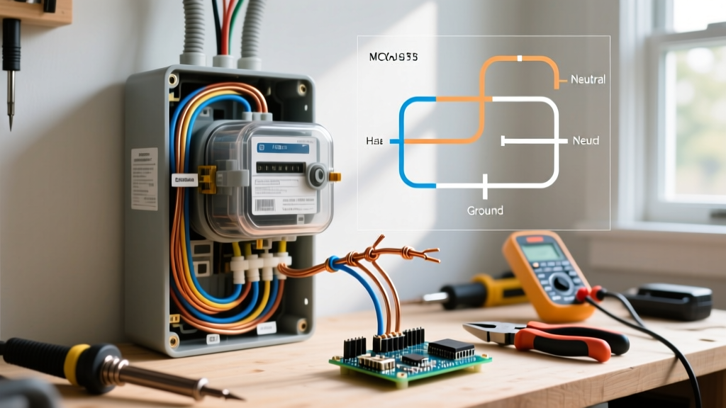
Unlike standard breakers, a GFCI breaker requires the neutral wire (white) from the load to connect directly to the breaker's neutral pigtail, not the neutral bus bar. The breaker's coiled white pigtail then connects to the panel's neutral bar.
- Line vs. Load: Ensure the incoming power from the utility connects to the "LINE" terminals, and the wires heading out to the pool connect to the "LOAD" terminals. Reversing these will render the GFCI protection useless.
- Torque Specifications: Use a calibrated inch-pound torque screwdriver to tighten the breaker lugs. The NFPA reports that loose connections are a leading cause of thermal failures and arc faults in residential panels. Torque to the manufacturer's spec (usually 35-45 in-lbs for 10 AWG wire).
Smart Timers vs. Mechanical Timers in 2026
The era of the loud, mechanical Intermatic T104 wind-up timer is fading. While still code-compliant, smart Wi-Fi timers like the Pentair IntellConnect or the Aqualink RS offer superior energy management. These devices integrate directly with variable-speed pumps (like the Pentair SuperFlo VS), allowing you to program low-speed filtration cycles that use up to 80% less electricity than single-speed 240V pumps. When wiring a smart controller, ensure the enclosure is rated for outdoor use (NEMA 3R) and mounted at least 5 feet horizontally from the pool's inside wall.
Common Failure Modes and Troubleshooting
Even with meticulous installation, above ground pool circuits can experience issues. Here is how to diagnose the most common 2026 service calls:
1. GFCI Nuisance Tripping
The Symptom: The breaker trips randomly, especially after heavy rain or morning dew, even when the pump is off.
The Fix: Moisture has infiltrated the conduit or the timer enclosure. Check all above-ground PVC joints; they must be glued with solvent cement, not just push-fitted. Ensure the conduit entering the pump junction box is sealed with a duct seal compound (like Gardner Bender GB-510) to prevent condensation from traveling down the wires into the motor housing.
2. Shared Neutral Errors
The Symptom: The GFCI breaker trips instantly upon reset.
The Fix: The pool circuit's neutral wire is touching or sharing a terminal with a neutral from a different circuit (like patio lighting) downstream of the GFCI. GFCI breakers monitor the exact current balance between the hot and neutral legs. Any neutral current returning via a different path will be interpreted as a ground fault. Isolate the pool neutral completely.
3. Voltage Drop on Long Runs
The Symptom: The pump hums, struggles to start, or runs hot.
The Fix: If your equipment pad is more than 100 feet from the main panel, 10 AWG wire may suffer from excessive voltage drop, starving the motor of amperage. Upsize the conductors in the conduit to 8 AWG THWN-2 to maintain optimal voltage delivery over long distances.
Final Inspection and Energization
Before filling the pool with water, schedule a rough-in and final inspection with your local Authority Having Jurisdiction (AHJ). The inspector will verify your trench depth, conduit glue joints, torque marks on the panel lugs, and the continuity of your #8 AWG bonding grid using a micro-ohmmeter. Only after receiving the green sticker should you fill the pool and energize the circuit. Properly executed, this electrical wiring for above ground pool infrastructure will provide decades of safe, efficient, and code-compliant operation.