
The Critical Role of Proper Electric Fan Relay Wiring
Upgrading to an auxiliary cooling system or replacing a failed HVAC blower motor requires more than just connecting wires to a battery. At the heart of high-current automotive and light-industrial cooling systems is the relay. Proper electric fan relay wiring isolates high-amperage loads from delicate low-amperage switches, thermostats, and ECU triggers. A poorly executed wiring job using undersized wire or non-ratcheting crimpers will inevitably lead to voltage drop, melted harnesses, and alternator failure.
This comprehensive material and tool guide breaks down the exact components, wire specifications, and professional-grade tools required to build a bulletproof relay circuit in 2026. Whether you are wiring a single 16-inch primary puller fan drawing 15 amps or a dual-fan setup pulling 30 amps, the principles of circuit protection and termination remain absolute.
Core Component Selection: The Relay and Circuit Protection
The industry standard for automotive and light-commercial electric fan relay wiring is the Bosch-style ISO mini relay. For a standard single electric cooling fan, a 4-pin SPST (Single Pole, Single Throw) relay is mandatory. Avoid 5-pin SPDT relays unless your specific circuit requires a secondary switched ground or accessory trigger.
Recommended Relay and Fuse Specifications
- Relay: Bosch 0332014150 (12V, 30A, 4-Pin SPST). Features a built-in resistor to suppress back-EMF voltage spikes that can fry solid-state thermostat switches or ECU drivers. Average cost: $6.50 - $8.00.
- Circuit Protection: Littelfuse MAXI Blade Fuses. For a continuous 15A fan load, the National Electrical Code (NEC) and SAE J1113 standards recommend sizing the fuse at 125% of the continuous load. Therefore, a 20A MAXI fuse is ideal for a 15A fan, while a 30A MAXI fuse is required for dual-fan setups drawing up to 25A.
Expert Insight: Never use standard ATO/ATC mini fuses for the main power feed of an electric fan. The high inrush current (locked rotor amps) when the fan motor initially starts can fatigue standard mini fuses over time, leading to nuisance blows. Always use MAXI or MIDI fuses for the main 10 AWG or 8 AWG power feed.
Material & Tool Matrix for Professional Termination
The most common point of failure in electric fan relay wiring is the terminal crimp. Soldering is strictly prohibited in high-vibration, high-temperature engine bay environments because solder wicks into the wire strands, creating a rigid point that fatigues and snaps. You must use mechanical crimping with adhesive-lined heat shrink.
| Item Category | Specific Recommendation | Purpose & Specification | Estimated Cost |
|---|---|---|---|
| Primary Wire | 10 AWG TXL (Cross-linked Polyethylene) | Rated to 150°C. Essential for engine bay routing near exhaust headers. Do not use THHN or standard PVC wire. | $0.85 / ft |
| Terminals | Delphi Packard Weather-Pack or Metra 70-0000 | Sealed, corrosion-resistant terminals designed specifically for Bosch-style relay sockets. | $0.40 / ea |
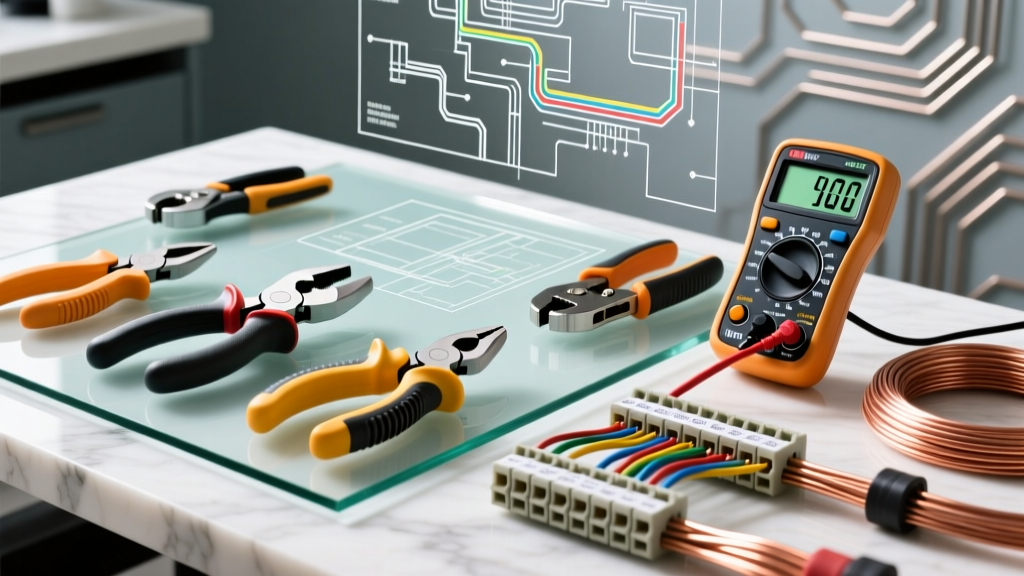
| Crimping Tool | Titan 11500 or Wirex Ratcheting Crimper | Ensures a gas-tight crimp with consistent pressure. Non-ratcheting pliers are unacceptable for 10 AWG wire. | $45.00 - $65.00 |
| Heat Shrink | 3M FP-301 Dual-Wall (Adhesive-Lined) | Melts and seals the terminal barrel, preventing moisture ingress and capillary action wicking. | $12.00 / spool |
| Inline Fuse Holder | Littelfuse MAXI Inline Waterproof Holder | Must be placed within 6 inches of the battery positive terminal to protect the entire main power run. | $8.50 |
Wire Gauge Sizing and Routing Strategy
Choosing the correct wire gauge is dictated by the amperage draw and the total length of the wire run (both positive and ground). Voltage drop is the enemy of electric fan motors; a drop of just 1 volt at the fan connector reduces cooling efficiency by up to 15% and drastically increases the heat generated by the motor windings.
Sizing Chart for Electric Fan Circuits
- Up to 15 Amps (Single Fan): 10 AWG TXL wire for runs up to 10 feet. Upgrade to 8 AWG if the run exceeds 10 feet or passes through high-ambient heat zones.
- 15 to 25 Amps (Dual Fans): 8 AWG TXL wire minimum. Requires a 40A rated relay (e.g., Bosch 0332209150) and a 30A MAXI fuse.
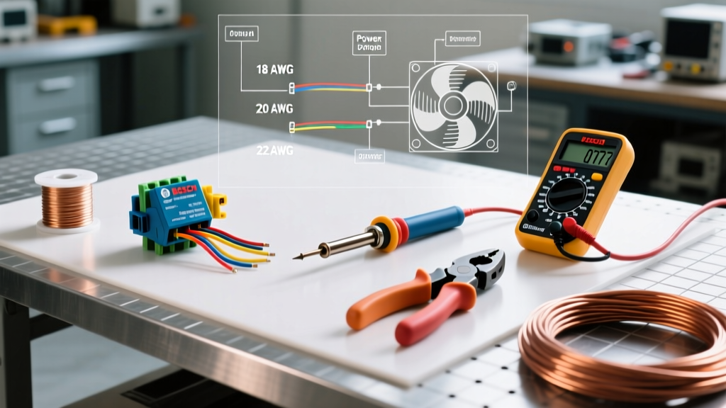
- Trigger Wire (Pins 85/86): 16 AWG or 18 AWG GXL wire is sufficient for the low-amperage signal coming from the thermostat switch or ECU.
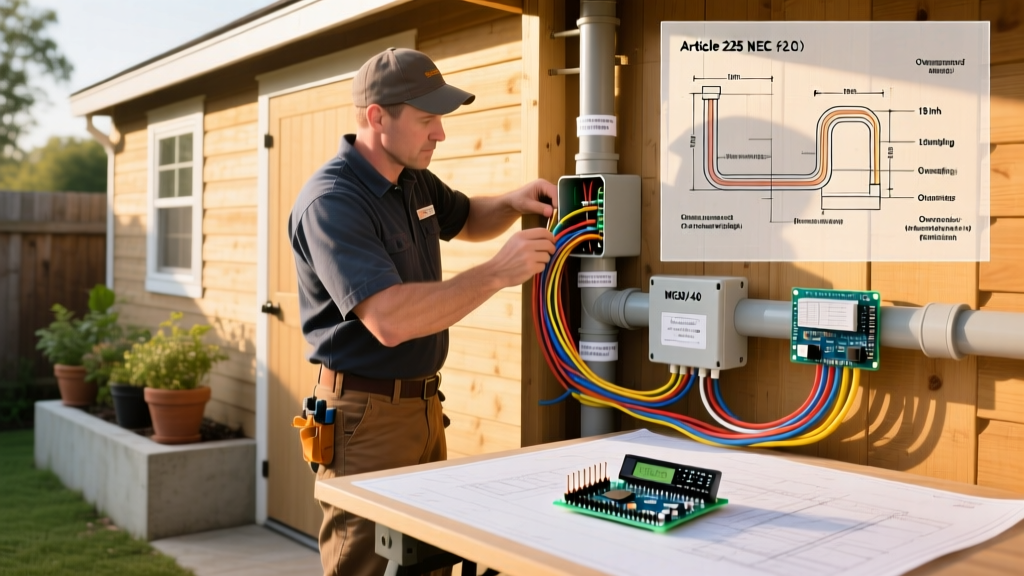
When routing the main power wire from the battery to the relay, always use split-loom tubing or braided fiberglass sleeving. Secure the harness every 8 inches using UV-resistant zip ties or aluminum P-clamps with rubber cushions. Never zip-tie wiring directly to sharp metal brackets or hot exhaust components.
Step-by-Step Terminal Crimping and Termination
Achieving a gas-tight crimp ensures that the metal of the terminal and the copper strands deform together, eliminating oxygen and preventing oxidation. Follow this exact sequence for 10 AWG TXL wire:
- Strip the Wire: Use a precision wire stripper (like the Klein 11055) to remove exactly 5/16" of insulation. Do not nick the outer copper strands; a nicked strand creates a stress riser that will snap under engine vibration.
- Prepare the Heat Shrink: Cut a piece of 3M dual-wall heat shrink so that it will cover the terminal barrel and extend 1/4" onto the wire insulation.
- Insert and Crimp: Insert the bare wire into the terminal barrel until it hits the internal stop. Place the terminal into the correct die of your ratcheting crimper (usually the red or 10-12 AWG notch). Squeeze the handles until the ratchet releases automatically.
- The Tug Test: Pull the wire and terminal in opposite directions with moderate force. A proper ratcheting crimp will not separate. If it pulls out, your stripper is removing too much copper or your crimper die is worn.
- Seal the Connection: Slide the adhesive-lined heat shrink over the crimp and apply heat with a dedicated heat gun (not a lighter or torch). Heat until the adhesive oozes slightly from both ends, indicating a complete environmental seal.
Understanding the Bosch-Style Pinout
Miswiring the relay pins is a frequent cause of dead shorts and blown fuses. The standard ISO mini relay pinout is stamped directly onto the plastic casing, but understanding the internal logic prevents catastrophic errors:
- Pin 30 (Common Input): Connects to the main 12V+ power feed from the battery (via the MAXI fuse holder).
- Pin 87 (Normally Open Output): Connects to the positive terminal of the electric fan motor.
- Pin 86 (Coil Positive): Connects to a switched 12V+ ignition source or direct battery power if triggered by a ground-switching thermostat.
- Pin 85 (Coil Ground/Trigger): Connects to the thermostat switch, ECU driver, or manual dashboard toggle switch.
Pro-Tip for ECU Triggering: If your engine management system (like a Holley Terminator X or Haltech Elite) triggers the fan relay via a ground-switched output, wire Pin 86 to a fused ignition 12V+ source, and wire Pin 85 to the ECU's programmable ground output. Never feed 12V+ directly into an ECU ground driver.
Testing and Diagnosing Voltage Drop
Once your electric fan relay wiring is complete, visual inspection is not enough. You must verify circuit integrity using a digital multimeter (DMM). According to testing guidelines published by Fluke Corporation, voltage drop testing must be performed while the circuit is under load (fan running).
The Voltage Drop Test Procedure
- Set your DMM to DC Volts.
- With the engine running and the fan engaged, place the red probe on the battery positive terminal and the black probe on the fan motor's positive input wire.
- The reading should be 0.5V or less. If it reads 1.2V, you have excessive resistance in the positive feed (likely a poor crimp at Pin 30 or Pin 87, or an undersized fuse holder).
- Next, test the ground side: place the red probe on the fan motor's negative terminal and the black probe on the battery negative terminal. Again, the drop must be under 0.5V.
Common Failure Modes and Edge Cases
Even with premium materials, specific environmental and electrical edge cases can compromise your installation. Being aware of these failure modes separates amateur DIYers from seasoned automotive electricians.
1. Back-EMF and Flyback Voltage Spikes
When the relay coil (pins 85/86) is de-energized, the collapsing magnetic field generates a high-voltage reverse spike (back-EMF). If you are using a cheap relay without an internal suppression resistor or diode, this spike travels back into the trigger wire, potentially destroying a solid-state thermostat or an ECU transistor. Always verify your relay has internal suppression, or solder a 1N4001 flyback diode across pins 85 and 86 (stripe facing Pin 86).
2. Thermal Fatigue at the Fuse Holder
Cheap, imported inline fuse holders often use thin brass contacts that lose their spring tension after repeated heat cycles. As detailed in Littelfuse automotive fuse documentation, poor contact pressure increases resistance, generating localized heat that melts the plastic housing. Always use name-brand MAXI fuse holders with heavy-gauge copper alloy contacts.
3. Grounding to Painted or Powder-Coated Surfaces
The electric fan motor ground must terminate at a bare, unpainted metal surface on the engine block or chassis. Powder coating and e-coat paint are electrical insulators. Use a wire brush or sandpaper to remove the coating, bolt the ring terminal securely, and then coat the bare metal with a dielectric grease or battery terminal protector spray to prevent galvanic corrosion.
Final Thoughts on Harness Reliability
Executing flawless electric fan relay wiring requires an upfront investment in the right tools and materials. By utilizing 10 AWG TXL wire, ratcheting crimpers, adhesive-lined heat shrink, and properly rated MAXI circuit protection, you create a harness that will outlast the vehicle itself. For further reading on automotive connector standards and environmental sealing, refer to the engineering resources provided by TE Connectivity. Never cut corners on termination; the reliability of your cooling system depends entirely on the integrity of your connections.