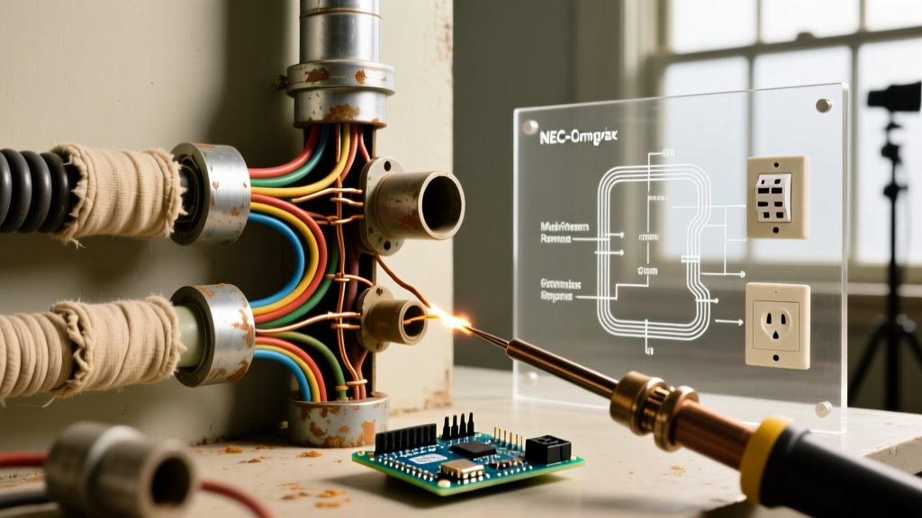

The 1940s Transition Era in Electrical Codes
The 1940s represented a pivotal transitional decade in residential and commercial electrical infrastructure. Driven by the post-World War II housing boom and the rapid electrification of rural America, the National Electrical Code (NEC) underwent significant revisions between the 1940, 1943, 1947, and 1949 editions. For modern electricians, inspectors, and homeowners, understanding 1940s electrical wiring is not just a historical exercise; it is a critical safety imperative. Millions of homes built during this era still contain original wiring systems that have long surpassed their intended 50-to-70-year lifespans.
"The 1940s marked the bridge between the open-wiring methods of the early 20th century and the concealed sheathed cable systems we rely on today. However, the materials used during this wartime and post-war era—specifically vulcanized rubber and early thermoplastics—present unique degradation profiles that modern inspectors must recognize."
This guide breaks down the specific wiring methods permitted under 1940s code cycles, identifies their modern failure modes, and outlines actionable, NEC-compliant upgrade pathways for 2026 and beyond.
Dominant Wiring Methods of the 1940s
During the 1940s, electricians utilized a mix of legacy systems and emerging technologies. Copper shortages during WWII also forced temporary shifts toward aluminum and steel-based wiring methods. Below is a breakdown of the three primary systems you will encounter in a 1940s property.
Comparison Matrix: 1940s Wiring vs. Modern Equivalents
| 1940s Wiring Method | Physical Characteristics | Modern NEC Equivalent | Primary Failure Mode Today |
|---|---|---|---|
| Knob & Tube (K&T) | Single conductors suspended on porcelain knobs, passing through joists via ceramic tubes. No outer sheath. | Non-Metallic (NM) Sheathed Cable (Romex) | Insulation crumbling at splice points; thermal damage from modern blown-in insulation. |
| Type AC (BX Cable) | Flexible interlocking steel armor housing rubber-insulated conductors. Often lacks an internal bonding strip. | Type MC or Type AC with Equipment Grounding Conductor (EGC) | Armor cutting into wire insulation at sharp bends; high-impedance ground path. |
| Early Type NM | Rubber-insulated conductors wrapped in a cotton, rayon, or asbestos outer braid. No bare ground wire. | Modern NM-B (PVC insulated with bare copper EGC) | Cotton braid absorbs moisture; rubber insulation turns brittle and flakes off. |
Critical Code Deficiencies by Today's Standards
While 1940s electrical wiring was installed to the legal standards of its day, it fundamentally violates several core safety mandates of the current NEC. Understanding these deficiencies is crucial for passing modern inspections and securing home insurance.
1. The Absence of an Equipment Grounding Conductor (EGC)
The most glaring deficiency in 1940s wiring is the lack of a dedicated ground wire. Under NEC Article 250, modern circuits require an EGC to provide a low-impedance path for fault currents, ensuring the breaker trips instantly during a short circuit. In 1940s Type AC (BX) cable, the steel armor was sometimes relied upon as a ground path. However, because early BX lacked the internal aluminum or copper bonding strip found in modern AC cable, the spiral steel armor exhibits high impedance. Under modern code, this armor is not recognized as a valid EGC.
2. Vulcanized Rubber Insulation Degradation
Before the widespread adoption of PVC (thermoplastic) insulation in the 1960s, 1940s cables relied on vulcanized rubber. Over 80 years, the plasticizers in this rubber evaporate. The insulation becomes rigid, brittle, and prone to cracking. When an electrician pulls a 1940s wire through a stud or simply bends it to attach a new receptacle, the rubber often shatters, exposing bare copper and creating an immediate arc-fault hazard.
3. Overcurrent Protection Mismatches
Many 1940s homes were originally equipped with 60-amp or 100-amp fuse panels. Over the decades, homeowners frequently upgraded to 15-amp or 20-amp circuit breakers without replacing the original #14 or #12 AWG wiring. Worse, some 1940s lighting circuits were wired with #16 or #18 AWG fixture wire that was improperly tied to 15-amp breakers, creating a severe fire risk where the wire melts before the breaker trips.
NEC-Compliant Upgrade Pathways
When dealing with 1940s electrical wiring, you generally have two code-compliant paths: a full rewire or a targeted mitigation strategy utilizing Ground Fault Circuit Interrupter (GFCI) technology.
Option 1: The Full Rewire (The Gold Standard)
A complete rewire involves abandoning the 1940s wiring in place (cutting it dead at the panel and capping it) and fishing modern NM-B or MC cable through the walls. 2026 Cost Expectation: Expect to pay between $12 to $18 per linear square foot for a full rewire of a 1,500 sq. ft. home, totaling $18,000 to $27,000 depending on regional labor rates and drywall repair costs. This is often the only way to satisfy strict underwriting requirements from major insurers like State Farm or Allstate for homes with active K&T or ungrounded rubber wiring.
Option 2: GFCI Protection for Ungrounded Receptacles
If a full rewire is financially unfeasible, the NEC provides a specific exception for replacing ungrounded (2-prong) receptacles. Under NEC 406.4(D)(2), you may replace a 2-prong receptacle with a 3-prong receptacle only if it is protected by a GFCI device. The GFCI does not create a ground; rather, it protects the user from lethal shock by detecting current imbalances as low as 4 to 6 milliamps.
Step-by-Step: Retrofitting a 1940s Ungrounded Receptacle
Follow this precise procedure to upgrade a 1940s ungrounded outlet while maintaining strict NEC compliance.
- Verify the Absence of Ground: Use a digital multimeter (e.g., Fluke 117) to test between the hot slot and the metal junction box. If you read 0V or a floating ghost voltage, confirm there is no valid EGC.
- Inspect the Wire Insulation: Gently pull the 1940s cloth/rubber wires into the box. If the rubber flakes off, you must cut the wire back to healthy insulation and use a Wire-Nut with a pigtail, or abandon the wire if insufficient length remains.
- Install the GFCI Receptacle: Connect the black (hot) wire to the brass LINE terminal and the white (neutral) wire to the silver LINE terminal. Do not use the LOAD terminals unless you are protecting downstream outlets.
- Apply Mandatory Labeling: NEC 406.4(D)(2) strictly requires the faceplate to bear the included adhesive label reading "GFCI Protected" and "No Equipment Ground." Failure to apply these stickers is an automatic inspection failure.
- Test the Circuit: Press the "TEST" button on the GFCI to ensure it trips, then reset. Use a plug-in GFCI tester to verify proper function.
Insurance and Real Estate Implications in 2026
Homeowners and real estate investors must recognize that 1940s electrical wiring is a major red flag during property transactions. Most standard home insurance policies will either deny coverage or mandate a surcharge of 15% to 30% if an inspector notes active Knob & Tube or ungrounded rubber-insulated wiring. Furthermore, modern smart home devices, surge protectors, and high-end AV equipment require a true equipment ground to function safely; plugging them into a GFCI-protected but ungrounded 1940s circuit will void the manufacturer's equipment warranty.
Authoritative Sources & Further Reading
To ensure your projects meet the highest safety standards, always consult the latest code cycles and authoritative safety organizations:
- NFPA 70: National Electrical Code (NEC) - The definitive standard for safe electrical design, installation, and inspection.
- U.S. Consumer Product Safety Commission (CPSC) Electrical Safety Guides - Vital resources on identifying hazards in older home wiring systems.
- U.S. Fire Administration (USFA) Electrical Fire Safety Outreach - Data and prevention strategies regarding electrical fires in aging housing stock.