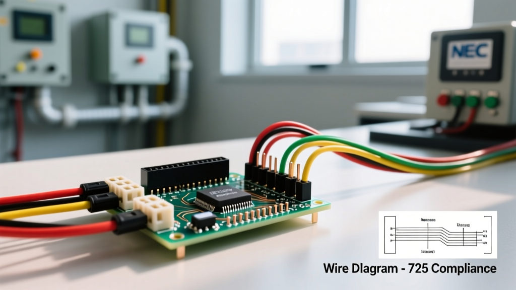

Bridging Microcontrollers and Commercial Loads
Integrating low-voltage microcontrollers into commercial building management systems (BMS) or light industrial automation requires strict adherence to electrical safety and code compliance. When wiring Arduino relay modules to switch commercial loads—such as 120V HVAC contactors, 24V damper actuators, or 277V lighting circuits—the margin for error shrinks dramatically. Unlike hobbyist breadboard projects, commercial environments demand robust optoisolation, strict adherence to NEC Article 725, and components rated for continuous industrial duty cycles. According to the U.S. Department of Energy, modern commercial buildings increasingly rely on edge-computing devices and microcontrollers for localized HVAC and lighting optimization, making safe relay integration a critical skill for automation technicians.
The Anatomy of a Commercial-Grade Relay Module
Before terminating any wires, you must understand the internal architecture of the relay module. A standard 5V relay module utilizes an electromechanical relay (EMR), a flyback diode, an indicator LED, and an optocoupler (typically a PC817). The optocoupler uses light to transmit the switching signal across a galvanic barrier, ensuring that high-voltage transients on the load side cannot travel back through the coil and destroy the microcontroller's GPIO pins.
The JD-VCC Jumper: A Critical Isolation Flaw
Most multi-channel Arduino relay boards feature a jumper labeled JD-VCC or VCC-JD. In its default position, this jumper bridges the logic-side power (from the Arduino) to the relay coil power. This completely defeats the optoisolation. For commercial wiring, you must remove this jumper and provide a dedicated, isolated 5V power supply for the relay coils (the JD-VCC and GND pins on the relay side), while the Arduino only connects to the signal inputs (IN1, IN2) and the logic ground. This prevents ground loops and ensures that a catastrophic failure on the 120V/240V side cannot energize the Arduino chassis or low-voltage wiring.
Code Alert: Under NFPA 70 (National Electrical Code) Article 725, Class 2 low-voltage control circuits must be physically separated from Class 1 line-voltage power circuits. Failing to isolate your Arduino wiring from commercial line voltage can result in failed inspections and severe shock hazards.
Step-by-Step: Wiring Arduino Relay for Commercial Loads
Follow this exact sequence to ensure galvanic isolation and code compliance when wiring your automation controller to commercial infrastructure.
- Establish Dual Power Supplies: Use your primary commercial 24VDC or 120VAC control transformer for the main logic, but step it down to an isolated 5VDC supply specifically for the relay coil side (JD-VCC).
- Remove the Isolation Jumper: Pull the plastic jumper cap off the JD-VCC pins on the relay module.
- Wire the Logic Side: Connect the Arduino digital output pins to the IN1, IN2 terminals. Connect the Arduino GND to the module's Logic GND. Do not connect the Arduino 5V to the JD-VCC.
- Wire the Coil Power Side: Connect the isolated 5VDC power supply to the JD-VCC pin and the supply ground to the Relay GND pin.
- Terminate the Load Side (COM/NO/NC): For commercial HVAC contactors, wire the Line voltage to the Common (COM) terminal, and the Load (contactor coil) to the Normally Open (NO) terminal. Ensure all line-voltage terminations are torqued to the manufacturer's specifications (typically 0.5 Nm for standard PCB screw terminals) to prevent arc faults.
- Verify Flyback Protection: Ensure the module has a 1N4007 flyback diode wired in reverse parallel across the relay coil. If switching highly inductive commercial loads (like large motor contactors), add an external RC snubber network (e.g., 100 ohms / 0.1µF) across the NO and COM terminals to suppress contact arcing.
Component Selection Matrix: Hobbyist vs. Commercial Modules
Not all relays are created equal. Using a hobbyist relay in a continuous-duty commercial panel is a leading cause of automation failure. Below is a 2026 market comparison of common relay solutions.
| Module Type | Relay Model | Contact Rating | Isolation Quality | Est. Price (2026) | Best Application |
|---|---|---|---|---|---|
| Hobbyist Board | Songle SRD-05VDC-SL-C | 10A @ 120VAC (Resistive) | Basic (PC817, shared ground risk) | $1.50 - $2.50 | Prototyping, temporary testing |
| Prosumer PCB | Omron G5LE-14-DC5 | 10A @ 250VAC / 30VDC | High (4000V dielectric strength) | $3.80 - $5.00 | Light commercial, custom BMS panels |
| Industrial DIN | Phoenix Contact PLC-RSC | 6A @ 250VAC (Slim profile) | Industrial (DIN rail, IP20 rated) | $25.00 - $32.00 | Heavy commercial, UL-listed panels |
Critical Failure Modes and Troubleshooting
When managing commercial automation, understanding how relays fail is just as important as knowing how to wire them. The Omron Relay Precautions Guide highlights several failure mechanisms that frequently plague improperly wired microcontroller circuits.
- Contact Welding (Inductive Inrush): A relay rated for 10A resistive may only handle 3A inductive. When switching commercial HVAC compressors or fluorescent lighting ballasts, the inrush current can be 6 to 10 times the steady-state current. This causes the internal contacts to micro-weld together, resulting in a relay that stays "ON" even when the Arduino sends a LOW signal. Solution: Use an Arduino to trigger a heavy-duty hardwired contactor, rather than passing the main load directly through the PCB relay.
- Optocoupler CTR Degradation: The Current Transfer Ratio (CTR) of the PC817 optocoupler degrades over time, especially in commercial electrical panels where ambient temperatures regularly exceed 40°C (104°F). After 5-7 years, the Arduino's 5V logic HIGH may no longer provide enough current to trigger the degraded optocoupler. Solution: Design your logic to drive the optocoupler with at least 15mA, well above the minimum threshold, to account for end-of-life degradation.
- Back-EMF Destruction: If the flyback diode fails or is omitted, the collapsing magnetic field of the relay coil generates a voltage spike exceeding 100V. This spike travels backward into the Arduino's ATmega328P or ESP32 microcontroller, permanently frying the GPIO pin or resetting the entire BMS edge node.
Code Compliance: NEC Article 725 and Separation
Commercial electrical inspectors will immediately flag any panel where low-voltage data wires are haphazardly zip-tied alongside 120V/277V line voltage wiring. Under NEC Article 725, Class 2 circuits (which includes your 5V Arduino logic and sensor wiring) must be separated from Class 1 power circuits by at least 2 inches, or separated by a grounded metal barrier or approved insulating divider.
When wiring your Arduino relay module inside a commercial NEMA 1 or NEMA 12 enclosure:
- Use slotted wire ducts with physical dividers to route 5V logic on the left and 120VAC line voltage on the right.
- Ensure all line-voltage screw terminals on the relay module are covered with IP20-finger-safe plastic guards to prevent accidental contact by maintenance personnel.
- Label all low-voltage wiring with commercial-grade heat-shrink markers indicating "CLASS 2 CONTROL WIRING".
Frequently Asked Questions (FAQ)
Can I use a standard 5V Arduino relay for 277V commercial lighting?
No. Standard hobbyist relays (like the Songle SRD-05VDC) are typically rated for 250VAC maximum. Commercial lighting in North America frequently operates at 277VAC (derived from 480Y/277V three-phase systems). Using a 250V rated relay on a 277V circuit violates UL listings and NEC code, and risks catastrophic dielectric breakdown. You must use a relay specifically rated for 300VAC or higher, or use the Arduino to trigger a 277V-rated hardwired contactor.
How do I prevent EMI from destroying the Arduino in a commercial panel?
Commercial panels are noisy environments filled with VFDs (Variable Frequency Drives) and heavy contactors. To protect your microcontroller, use shielded twisted-pair (STP) cable for all Arduino sensor inputs, ground the shield at the panel backplane only, and utilize optoisolated relay modules to maintain a physical galvanic barrier between the noisy line-voltage side and the sensitive 5V logic side.