
The Modern Reality of Range Circuits: What Changed in the NEC
Wiring an electric stove is one of the most demanding DIY electrical projects in a residential setting. Unlike standard 120V lighting circuits, a modern electric range requires a dedicated 240V circuit capable of delivering massive current draws—often exceeding 12,000 watts during peak usage (e.g., when all burners and the oven are engaged simultaneously). However, the most critical shift in recent years isn't about amperage; it is about ground-fault protection.
Under recent updates to the National Electrical Code (NEC), specifically Article 210.8(D), GFCI protection is now mandated for 250V receptacles rated at 50 amps or less that supply kitchen countertops and appliance areas. This means the days of simply installing a standard 50-amp double-pole breaker are over in most jurisdictions. You must now factor in the cost and installation requirements of a 50-amp GFCI breaker, fundamentally changing how you approach wiring an electric stove in new construction or full kitchen remodels.
Circuit Specifications & Material Breakdown
Before pulling any wire, you must verify your electrical panel's capacity and gather the correct, code-compliant materials. Using undersized wire or mismatched NEMA configurations is a primary cause of residential electrical fires.
| Component | Specification | Estimated Cost (2026) |
|---|---|---|
| Circuit Breaker | 50-Amp Double-Pole GFCI (e.g., Square D HOM250GFI or Eaton BR250GFI) | $75.00 - $95.00 |
| Wiring | 6/3 NM-B (Romex) with Ground, Copper (e.g., Southwire) | $5.00 - $6.50 / ft |
| Receptacle | NEMA 14-50R, 50-Amp, 125/250V (e.g., Leviton 279-S00) | $15.00 - $25.00 |
| Wall Plate | Single-gang, 2.156-inch opening (NEMA 14-50 compatible) | $3.00 - $8.00 |
| Torque Tool | Calibrated Torque Screwdriver (e.g., CDI Torque 401SM) | $45.00 - $80.00 |
Pro-Tip on NEMA Configurations: Never attempt to wire a 50-amp breaker to a NEMA 10-50 or 14-30 receptacle. The physical blade configurations exist specifically to prevent this. Always reference a reliable NEMA configuration guide to ensure your plug matches your receptacle and breaker rating.
Why 6/3 NM-B and Not Aluminum?
While aluminum SER (Service Entrance) cable is cheaper and often used by contractors for main panel feeders, 6 AWG aluminum is generally not rated for 50 amps in residential branch circuits under standard 75°C terminal ratings. Stick to 6 AWG Copper NM-B for indoor, dry-location stove runs. If you are running wire through a wet location or outdoors, you must use individual THHN/THWN-2 wires inside a rigid metal or PVC conduit.
Step-by-Step Installation: Panel to Receptacle
Follow this sequence to ensure a safe, code-compliant installation. Always verify local permits and OSHA electrical safety guidelines before working inside a live panel.
- De-energize the Main Panel: Shut off the main service disconnect. Use a non-contact voltage tester and a digital multimeter to verify that the bus bars are completely dead.
- Install the GFCI Breaker: Snap the 50-amp GFCI breaker onto the bus bars. Note that GFCI breakers are wider than standard breakers and require two full slots. Connect the neutral pigtail from the breaker directly to the panel's neutral bar. Do not leave this pigtail unconnected, or the GFCI test button will not function.
- Strip and Terminate Panel Connections: Strip exactly 3/4 inch of insulation from the black, red, and white wires. Insert the black and red wires into the breaker's hot lugs, and the white wire into the breaker's neutral lug. The bare copper ground goes to the panel's ground bar.
- Apply Exact Torque: This is where most DIYers fail. Use a torque screwdriver set to the manufacturer's specification (typically 40 in-lbs for 6 AWG copper on Square D or Eaton breakers). Loose lugs cause high resistance, leading to arcing, melted insulation, and panel fires.
- Route the Cable: Run the 6/3 NM-B from the panel to the receptacle location. Secure the cable with staples within 8 inches of the panel and every 4.5 feet thereafter. Maintain at least 1.25 inches of clearance from the face of framing members to prevent drywall screw punctures.
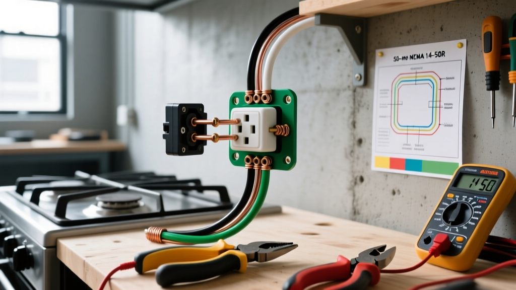
- Terminate the NEMA 14-50R Receptacle: Strip the outer jacket of the NM-B cable, leaving at least 8 inches of working wire inside the single-gang deep box. Connect the bare ground to the green terminal, the white neutral to the silver terminal (this is critical—the neutral must align with the W slot), and the red/black hots to the brass X and Y terminals.
The 4-Prong Cord Conversion: A Critical Safety Step
If you are wiring an electric stove in a home built before 1996, you will likely encounter a legacy 3-prong NEMA 10-50 receptacle. The NEC (Article 250.140) officially banned 3-prong range installations in new construction because it used the neutral wire as a ground path. If the neutral ever disconnected, the entire metal chassis of the stove would become energized at 120V.
WARNING: When upgrading from a 3-prong cord to a modern 4-prong cord (NEMA 14-50P), you must remove the bonding jumper (a small metal strap or green wire) on the back of the stove's terminal block. This strap connects the neutral terminal to the stove's metal chassis. In a 4-prong setup, the neutral and ground are strictly separated. Leaving the bonding strap in place creates a parallel neutral path, which is a severe code violation and shock hazard.
How to Wire the 4-Prong Pigtail to the Range
- Ground (Green): Connect to the dedicated green grounding screw on the stove chassis.
- Neutral (White): Connect to the center silver terminal on the block. Ensure the bonding strap is removed and tucked away.
- Hot 1 (Black) & Hot 2 (Red): Connect to the outer brass terminals. Polarity between the two hots does not matter for 240V heating elements.
Troubleshooting Common Wiring Failures
Even with careful installation, specific failure modes can occur. Use this diagnostic matrix to identify issues before calling an electrician.
| Symptom | Probable Cause | Diagnostic Fix |
|---|---|---|
| Stove clock and lights work, but burners won't heat. | Lost 240V leg. One of the hot wires is disconnected or the breaker is only half-tripped. | Test voltage across the X and Y slots on the receptacle. It must read ~240V. If it reads 120V, check the breaker lugs. |
| 120V components (clock, control board) fry or blow fuses immediately. | Reversed neutral and ground, or neutral connected to a hot leg at the receptacle. | Verify the white wire is on the silver (W) terminal and bare copper is on the green (G) terminal. |
| GFCI breaker trips instantly when the oven door is opened or closed. | Neutral-to-ground fault inside the appliance, or the bonding strap was left on during a 4-prong conversion. | Inspect the range terminal block. Remove the bonding jumper immediately. |
| Receptacle face feels warm to the touch after baking. | Undersized wire, loose terminal connections, or back-stabbed receptacle (though 14-50R only accepts screw terminals). | Check torque on receptacle screws. Ensure wire is wrapped clockwise around the screw terminal, not just pushed under. |
Final Commissioning and Testing
Once all terminations are complete and the wall plate is installed, restore power at the main panel. Press the 'Test' button on the 50-amp GFCI breaker; it should trip audibly. Reset it. Next, plug in the electric stove. Turn on a surface burner to high and the oven to 400°F. Use a clamp meter on one of the hot legs at the panel to verify the amperage draw is within the expected range (typically 15-25 amps during initial heat-up). Finally, use a multimeter to measure the voltage between the stove's metal chassis and a known ground (like a nearby water pipe); it should read 0.00V. If you read any voltage, immediately shut off the breaker and re-inspect your neutral/ground separation.