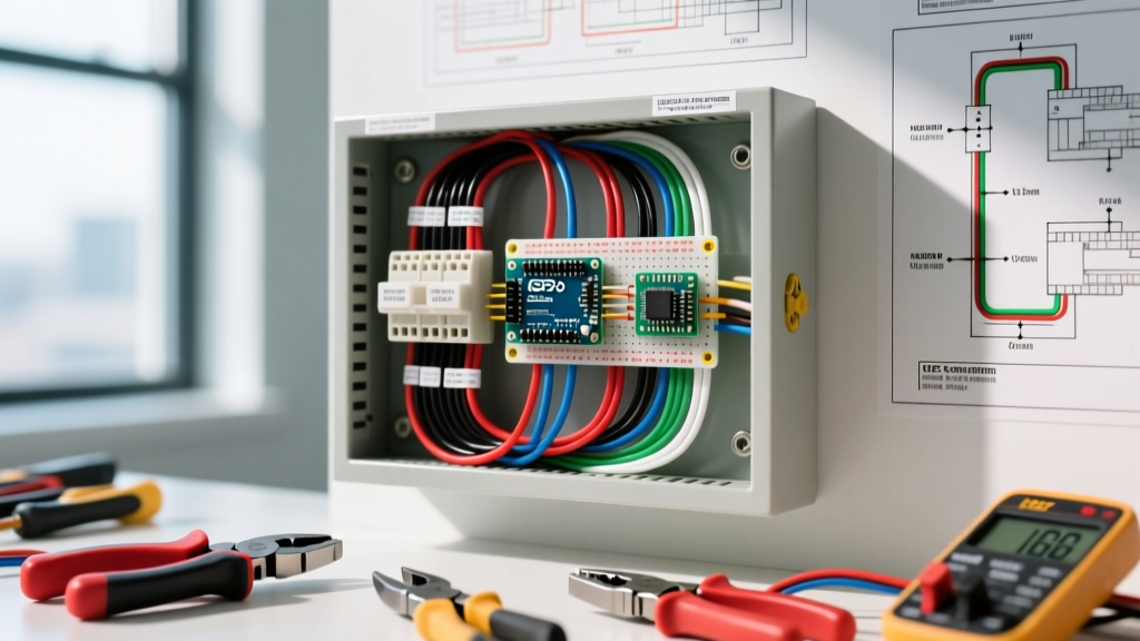

The Art and Science of Panel Dressing
There is a distinct difference between a panel that merely passes inspection and one that showcases true craftsmanship. Achieving neat electrical panel wiring is not just about aesthetics; it is a critical safety measure that improves thermal dissipation, simplifies future troubleshooting, and ensures strict compliance with the National Electrical Code (NEC). According to NFPA 70 (NEC) Article 110.12, mechanical execution of work must be 'neat and workmanlike.' Inspectors increasingly use this clause to reject 'spaghetti' panels where wires cross randomly, impede airflow, or obscure breaker labels.
In this step-by-step walkthrough, we will cover the exact techniques, tooling, and measurements required to dress a standard 200A residential load center (such as a Square D Homeline or Siemens QP series) to master electrician standards.
Phase 1: The Pre-Flight Tooling Checklist
You cannot achieve professional results with amateur tools. Before stripping a single wire, assemble the following specific gear:
- Wire Strippers: Klein Tools 11055 (for 10-18 AWG solid wire). Dull strippers nick the copper, creating hot spots.
- Torque Screwdriver: Wiha 320P8 or CDI 401SM. As of the 2020 NEC (and carried into 2023/2026 revisions), NEC 110.14(D) mandates the use of calibrated torque tools for all terminations.
- Wire Benders: Gardner Bender 1/2-inch plastic wire looms or custom 3D-printed TPU wire combs to maintain uniform spacing.
- Labeling System: Brady BMP21-PLUS with continuous vinyl tape for durable, smudge-proof circuit identification.
Estimated Tooling Cost: $250 - $350 for a professional-grade panel dressing kit. This investment pays for itself on the very first job through time saved and zero rejected inspections.
Phase 2: Cable Entry and the 8-Inch Rule
The foundation of neat electrical panel wiring begins before the wires even reach the breakers. When feeding NM-B (Romex) cables into the panel knockout holes, use 3/4-inch plastic non-metallic cable connectors. Avoid metal clamps for residential NM-B, as they can easily crush the outer jacket and damage the inner THHN insulation if over-tightened.
Managing the Slack
Once inside the panel, strip the outer NM-B jacket exactly at the point where it enters the connector. Do not leave jacketed cable running up the side of the panel box. For the individual conductors, leave exactly 8 to 10 inches of slack past the breaker or neutral bar. This provides enough length to route the wire to the furthest breaker in the panel without stretching, while preventing excess wire from bunching up in the center gutter.
Phase 3: Grounding and Neutral Routing (The Backbone)
The most common cause of panel clutter is the improper routing of grounding and neutral conductors. These wires form the 'backbone' of your panel dressing.
Main Panel vs. Subpanel Separation
Before routing, verify your panel type. In a main service panel, the neutral and ground bars are bonded. In a subpanel, Schneider Electric technical bulletins and NEC 250.142 strictly require the neutral bar to be isolated from the ground bar. Mixing these in a subpanel creates parallel neutral paths, which is a severe shock and fire hazard.
Pro Routing Technique: Route all ground wires down the left side of the panel gutter and all neutral wires down the right side. Use a 90-degree bend exactly 1 inch from the termination point so the wire lays flat against the back wall of the panel before rising to the bus bar. Never let a ground wire cross over the center gutter to reach the neutral bar.
Phase 4: Hot Conductor Routing and Wire Combs
This is where neat electrical panel wiring transitions from functional to artistic. The hot conductors (black, red, or blue THHN) must be routed cleanly to their respective single-pole or double-pole breakers.
Step-by-Step Hot Wire Dressing
- Group by Phase: Separate the hot wires into two groups corresponding to Phase A (left breakers) and Phase B (right breakers).
- The Center Gutter Sweep: Bring the Phase A wires up the left side of the center gutter, and Phase B wires up the right side. Do not allow wires to crisscross the middle of the gutter.
- Implement Wire Combs: About 3 inches below the breaker stabs, place a plastic wire comb or loom. This forces the wires into a perfectly straight, uniform bundle.
- The 90-Degree Break: At the exact height of the breaker terminal, bend the wire at a sharp 90-degree angle toward the breaker. Use your thumb and index finger to crease the wire, or use a dedicated wire bending jig to ensure every wire has the exact same bend radius.
- Trim and Strip: Cut the wire so it enters the breaker terminal with no exposed copper outside the lug, and no insulation pushed inside the lug. For standard 12 AWG wire, a strip length of 7/16-inch is usually perfect for Square D QO and Siemens QP breakers.
Phase 5: Torque Specifications and Termination
Hand-tightening lugs is a relic of the past. Under-torquing leads to thermal expansion/contraction cycles that loosen the connection over time, causing arcing and fires. Over-torquing strips the aluminum threads on the breaker lug or crushes the copper strand, reducing the wire's ampacity.
| Wire Gauge (THHN/THWN) | Strip Length | Min. Bend Radius (NEC Ch. 9) | Target Torque (in-lbs) |
|---|---|---|---|
| 14 AWG | 3/8 inch | 1.0 inch | 12 - 15 in-lbs |
| 12 AWG | 7/16 inch | 1.25 inches | 15 - 20 in-lbs |
| 10 AWG | 1/2 inch | 1.5 inches | 30 - 35 in-lbs |
| 8 AWG (Stranded) | 5/8 inch | 2.0 inches | 40 - 45 in-lbs |
Note: Always verify the specific torque value printed on the breaker label or the manufacturer's data sheet, as lug designs vary between Eaton BR, Siemens QP, and Square D Homeline.
Phase 6: Final Dressing, Lacing, and Labeling
Once all wires are terminated and torqued, perform the final dressing.
- Cable Lacing: While zip ties are common, they can over-tighten and deform wire insulation over decades. Professional electricians increasingly use Velcro-style hook-and-loop wraps (like Panduit cable ties) or traditional waxed cable lacing cord to bind the neutral and ground bundles every 6 inches.
- Labeling: Use a thermal transfer printer (like the Brady BMP21-PLUS) to label both ends of every circuit. Do not rely on Sharpies and masking tape, which fade and peel within a few years due to the ambient heat inside the panel (which can reach 104°F / 40°C in a fully loaded summer panel).
- Debris Removal: Use a microfiber cloth and a soft-bristle brush to remove all copper clippings and stripped insulation pieces from the bottom of the panel. A stray copper snippet can easily bridge a bus bar and cause a catastrophic dead short when the panel is energized.
Common Edge Cases and Failure Modes
Even with a meticulous plan, certain edge cases can ruin an otherwise perfect panel dressing job. Watch out for these specific pitfalls:
1. The 'Pigtail' Spaghetti
When installing AFCI or GFCI breakers, you must connect the circuit's neutral wire to the breaker's pigtail, not the neutral bar. If you have multiple AFCI breakers, the pigtails can create a massive tangle in the center gutter. Solution: Route the pigtail neutral wires directly behind the hot wires, hugging the breaker face, and secure them to the hot wire bundle using a small piece of Velcro tie. This hides the pigtails and keeps the center gutter clear.
2. Cross-Threading Aluminum Lugs
Breaker lugs are typically made of tin-plated aluminum. If you force the brass or steel screw of the torque screwdriver at an angle, you will cross-thread the soft aluminum, ruining the breaker. Solution: Always start the screw by hand or with a manual driver for the first three turns to ensure the threads are perfectly aligned before applying the calibrated torque tool.
3. Over-Stripping THHN Insulation
Stripping 3/4-inch of insulation off a 12 AWG wire 'just to be safe' results in exposed copper sitting outside the breaker lug. This is an immediate inspection failure and a shock hazard. Solution: Calibrate your Klein 11055 strippers to the exact depth of the breaker lug. If you over-strip, do not wrap the exposed copper in electrical tape (a massive red flag for inspectors). Instead, cut the wire back and re-strip it to the correct 7/16-inch length.
Summary: The ROI of Neatness
Mastering neat electrical panel wiring takes roughly 45 to 60 minutes longer per panel than a rushed 'slap-in' job. However, the return on investment is immense. A cleanly dressed panel dissipates heat more effectively, extending the lifespan of the breakers by reducing ambient thermal stress. Furthermore, when a homeowner or future technician needs to trace a fault at 2:00 AM, your logical routing, clear separation of phases, and durable labeling will turn a potential nightmare into a simple 5-minute fix. Treat every panel as a permanent monument to your trade expertise.