
Mastering the Trailer Electric Brake Wiring Diagram: An Installation Planning Guide
Towing a trailer exceeding 3,500 pounds requires flawless brake synchronization between your tow vehicle and the trailer axles. Relying on a generic, hastily sketched wiring schematic often leads to voltage drop, uneven braking, and catastrophic failure modes on long downhill grades. Before you cut a single inch of copper or mount a junction box, you must develop a comprehensive installation plan. This guide deconstructs the electric brake wiring diagram from an engineering perspective, focusing on wire sizing, component selection, and circuit routing to ensure your trailer meets both safety standards and real-world performance demands.
The Blueprint: Sourcing Components and Wire Selection
The most common failure in trailer braking systems is not the brake controller itself, but the wiring infrastructure. Standard big-box store trailer wire kits often use 14 AWG or 16 AWG stranded wire with cheap PVC insulation. This is unacceptable for electric brakes.
Bill of Materials (BOM) for a Tandem-Axle Setup
- Brake Controller: Tekonsha Prodigy P3 (Approx. $175) or Curt Spectrum (Approx. $140). Both offer proportional braking with digital diagnostics.
- Trailer Connector: Pollak 7-Way RV-Style Trailer Connector (Part #PK12-707E). Features heavy-duty copper pins and a spring-loaded dust cover.
- Junction Box: Pollak 7-Way Junction Box (Part #PK12-707). Essential for terminating axle wires and protecting connections from road debris.
- Main Brake Feed Wire: 10 AWG GXL (Cross-linked polyethylene). GXL insulation withstands engine bay temperatures up to 125°C and resists abrasion far better than standard THHN or PVC.
- Terminals: Adhesive-lined heat-shrink ring terminals and butt splices. Never solder trailer wiring. Solder wicks into the stranded wire, creating a rigid point that will fatigue and snap under constant highway vibration.
A standard 10-inch Dexter Nev-R-Adjust brake magnet draws roughly 3.0 to 4.0 amps at 12V. Four magnets draw up to 16 amps. Using 14 AWG wire for a 30-foot run (60 feet round-trip) results in a voltage drop of over 2.5 volts under load. This starves the rear axle magnets, causing the front axle to do all the work, leading to premature wear and trailer sway. Always use 10 AWG for the main blue brake feed and the white ground return.
Interpreting the 7-Way RV Blade Pinout Matrix
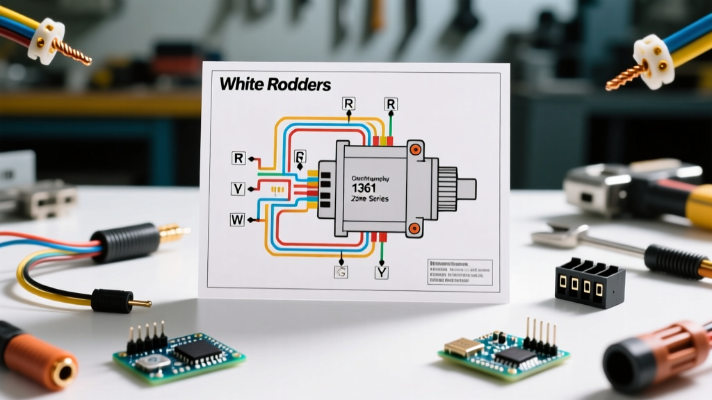
The 7-way RV blade connector is the industry standard for electric brake trailers. Misinterpreting the pinout or undersizing the ground wire are the leading causes of melted trailer plugs. Below is the definitive wiring matrix for your installation plan.
| Pin Position | Function | Wire Color | Minimum Gauge | Installation Notes |
|---|---|---|---|---|
| 1 (Ground) | Chassis Ground | White | 8 AWG or 10 AWG | Must be bolted directly to the trailer frame, sanded to bare metal. |
| 2 (Tail) | Running Lights | Brown | 14 AWG | Feed to all marker and tail lights. |
| 3 (Left) | Left Turn/Stop | Yellow | 14 AWG | Route down the driver side frame rail. |
| 4 (Aux) | 12V Auxiliary | Black | 10 AWG | Used for breakaway battery charging and interior trailer power. |
| 5 (Right) | Right Turn/Stop | Green | 14 AWG | Route down the passenger side frame rail. |
| 6 (Brakes) | Electric Brakes | Blue | 10 AWG | Primary feed from brake controller to junction box. |
| 7 (Reverse) | Reverse Lights | Purple | 14 AWG | Optional: Used to disable surge brakes or power reverse lamps. |
Routing the Breakaway Switch Circuit
The breakaway switch is a critical, legally mandated safety device. If the trailer detaches from the hitch, a lanyard pulls a pin from the switch, applying full 12V power directly to the brake magnets to lock the trailer wheels and prevent a runaway incident.
Common Wiring Mistake to Avoid
Many DIYers incorrectly wire the breakaway switch to the blue brake feed wire after it passes through the brake controller. This is fundamentally flawed. If the 7-way plug shears off during a breakaway event, the circuit to the controller is severed, rendering the breakaway switch useless.
The Correct Routing: The breakaway switch must be wired directly to a dedicated 12V breakaway battery (typically a 12V 5Ah Sealed Lead Acid battery mounted on the trailer tongue). One wire from the switch goes to the positive terminal of the battery. The other wire from the switch splices directly into the main 10 AWG blue brake feed wire between the 7-way plug and the junction box, completely bypassing the tow vehicle.
Axle Wiring Strategies: Daisy-Chain vs. Home-Run
When wiring the individual brake assemblies (such as Dexter 10-inch Nev-R-Adjust units), you have two topological choices. Your electric brake wiring diagram must specify which method you will use before drilling holes in your frame.
1. The Daisy-Chain Method (Not Recommended)
This involves running the blue power wire from the front axle magnet, splicing it, and continuing it to the rear axle magnet. The white ground wire is daisy-chained similarly. While this saves wire, it creates multiple splice points under the trailer, exposed to water, salt, and gravel. A single corroded splice disables the rear brakes.
2. The Home-Run Method (Industry Best Practice)
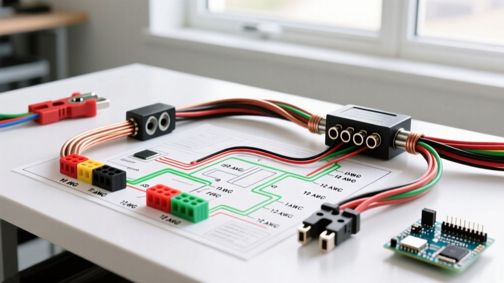
Run a dedicated 12 AWG blue wire and 12 AWG white wire from each individual brake magnet directly back to the central Pollak junction box mounted near the trailer tongue. Inside the junction box, all blue wires are terminated under a single bus bar connected to the main 10 AWG feed. All white wires terminate on the ground bus bar. This isolates each brake magnet, making multimeter troubleshooting trivial and ensuring that a severed wire on the rear axle does not affect the front axle.
Pre-Flight Continuity and Resistance Testing
Before sealing the junction box or mounting the 7-way plug cover, you must validate the circuit integrity using a digital multimeter. According to guidelines supported by the Federal Motor Carrier Safety Administration (FMCSA), commercial and heavy-duty trailer braking systems must undergo rigorous electrical validation to ensure stopping compliance.
- Magnet Resistance Check: Set your multimeter to Ohms (Ω). Probe the two wires of a single Dexter brake magnet. A healthy 12V magnet will read between 3.0 and 4.0 ohms. If it reads infinite (OL), the internal coil is broken. If it reads near 0.0, the magnet is shorted.
- Parallel Circuit Validation: With all four magnets wired to the junction box, probe the main blue feed and the main white ground at the tongue. Because the magnets are wired in parallel, the total resistance should drop. Four 3.5-ohm magnets in parallel will yield a total circuit resistance of approximately 0.87 ohms.
- Ground Integrity Test: Measure resistance between the white ground wire at the tongue and the bare metal chassis of the rear axle. It should read less than 0.5 ohms. Any higher indicates a poor frame ground that will cause voltage starvation.
Compliance and Authoritative References
Adhering to proper wire ampacity and insulation standards is not just about performance; it is a matter of legal and physical safety. When selecting your wire gauges and routing paths, always cross-reference your plans with the National Fire Protection Association (NFPA 70) National Electrical Code guidelines for mobile and automotive DC applications. Furthermore, manufacturers building recreational trailers must adhere to strict electrical safety codes established by the RV Industry Association (RVIA), which mandate specific overcurrent protection and wire routing protocols to prevent chassis fires.
By treating your electric brake wiring diagram as a strict engineering blueprint rather than a rough sketch, you ensure that your trailer will stop predictably, safely, and reliably, regardless of the payload or the grade of the road ahead.