
Why Panel Schematics Rely on Standardized Wiring Diagram Electrical Symbols
When transitioning from basic residential wiring to commercial switchgear and industrial panel boards, the complexity of the schematics increases exponentially. At the heart of these blueprints are wiring diagram electrical symbols. These symbols are not merely abstract drawings; they are a precise, standardized language that dictates how power is distributed, metered, and protected. Misinterpreting a single symbol on a 480V single-line diagram can lead to catastrophic arc flash incidents, equipment destruction, or severe NEC code violations.
In North America, electrical symbols are primarily governed by the ANSI/IEEE 315 standard, alongside specific requirements outlined in the NFPA 70 National Electrical Code (NEC). However, as global supply chains integrate more European-manufactured switchgear into US facilities, understanding the IEC 60617 standard is equally critical for modern electrical engineers and master electricians.
Expert Insight: Never assume a breaker symbol implies fault-interrupting capacity. A standard disconnect switch symbol (often confused with a breaker by novices) will explode if opened under a short-circuit fault. Always verify the specific device designation (e.g., 'Q' for IEC power circuits, 'CB' for NEMA) alongside the graphic symbol.
The ANSI/NEMA vs. IEC Divide in Switchgear
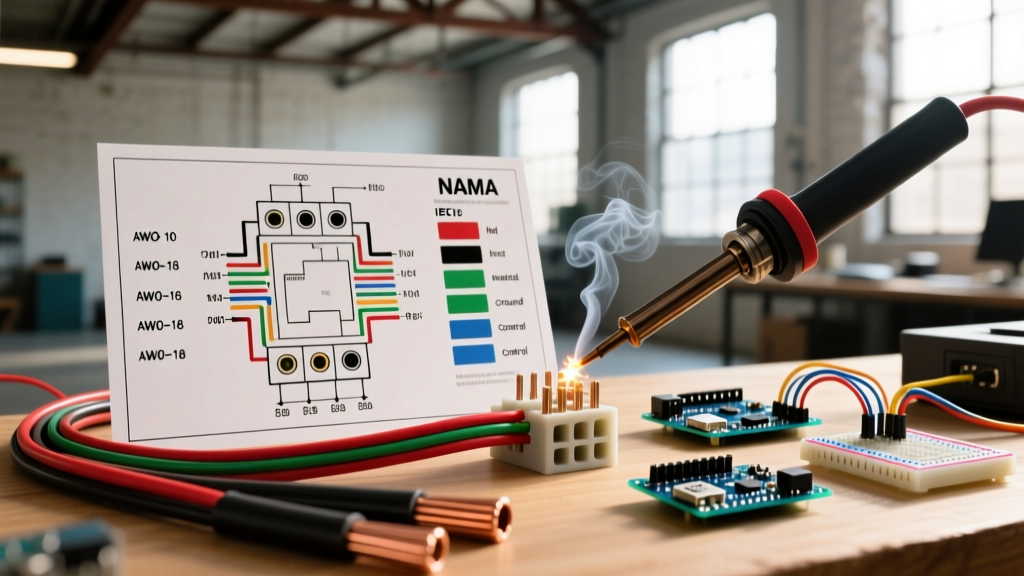
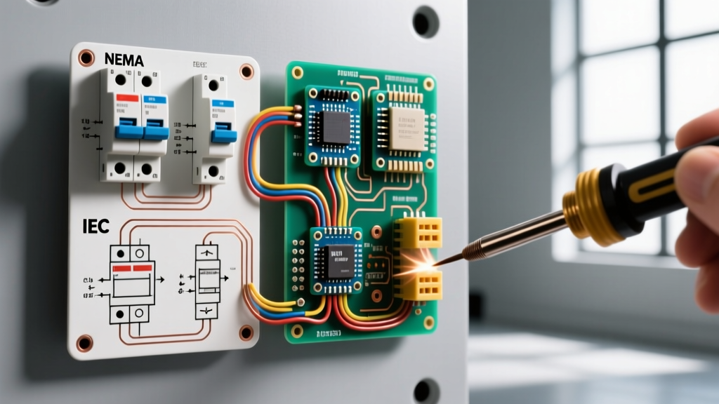
Before tracing a single busbar, you must identify which symbol library the drafting engineer utilized. NEMA (National Electrical Manufacturers Association) and IEC (International Electrotechnical Commission) use fundamentally different visual logic.
- NEMA/ANSI Logic: Tends to be more pictorial and detailed. A circuit breaker is often depicted as a rectangle with a line through it, or a specific switch symbol with a thermal/magnetic trip overlay.
- IEC Logic: Highly abstract and minimalist. A circuit breaker is typically represented by a simple 'X' on a straight line, while a disconnect switch is a simple angled line breaking the circuit.
According to NEMA standards publications, maintaining consistency within a single facility's documentation is paramount. Mixing NEMA control symbols with IEC power symbols on the same panel schedule is a leading cause of troubleshooting errors during emergency outages.
Comparison Matrix: Core Panel & Breaker Symbols
Below is a critical reference matrix for the most common wiring diagram electrical symbols found in commercial panel boards and motor control centers (MCCs).
| Component | NEMA / ANSI Symbol Description | IEC 60617 Symbol Description | Typical Panel Application |
|---|---|---|---|
| Circuit Breaker (Thermal-Magnetic) | Rectangle intersected by a diagonal line, often with a thermal curve overlay. | A straight line broken by an 'X' or a box with an 'X' inside. | Main feeder protection, branch circuit panels. |
| Disconnect Switch (Non-Load Break) | A blade-style switch symbol with a distinct gap, no trip mechanism shown. | A straight line broken by an angled, open blade. | Isolation upstream of VFDs or MCC buckets. |
| Current Transformer (CT) | Two overlapping circles on the conductor line. | A single circle with a line passing through the center. | Panel metering, ground fault sensing, revenue billing. |
| Shunt Trip (ST) | A solenoid coil symbol attached to the breaker mechanism latch. | A rectangle with 'ST' or a specific coil designation linked to the 'X'. | Fire alarm drop-out, emergency stop integration. |
| Surge Protective Device (SPD) | A box with a varistor symbol (a line with a sharp 'V' bend) to ground. | A box with a specific spark gap or varistor icon connected to PE. | Main switchboard transient protection (NEC 2023/2026 required in many services). |
Deep Dive: Decoding Microprocessor Trip Unit Symbols
In modern commercial switchboards (typically 800A to 4000A main bus ratings), standard thermal-magnetic breakers are replaced by electronic trip circuit breakers. The wiring diagram electrical symbols for these devices include specific designations for their trip curves, commonly referred to as LSIG.
The LSIG Designation
- L (Long-Time Delay): Protects against overloads. The symbol often includes an inverse-time curve graphic.
- S (Short-Time Delay): Allows downstream breakers to clear minor faults before the main breaker trips (selective coordination).
- I (Instantaneous): Trips immediately on massive short-circuit faults, bypassing all delays.
- G (Ground Fault): Detects residual current returning through the ground path. The symbol will explicitly show a core balance CT or a neutral-to-ground sensor loop.
When reading the panel schematic, look for the 'G' designation. Under current NEC guidelines and OSHA electrical safety mandates, ground-fault protection of equipment (GFPE) is strictly required on solidly grounded wye services of 480Y/277V, 1000A or more. If the single-line diagram lacks the GFPE sensor symbol on a 1200A main, the panel is fundamentally non-compliant.
Step-by-Step: Tracing a 480V Commercial Single-Line Diagram
To truly master wiring diagram electrical symbols, you must read them in context. Let us trace power through a standard 1200A commercial distribution panel.
Step 1: The Utility Source and Transformer
Power enters from the left. You will see a utility source symbol (often an arrow pointing into a box) feeding a Delta-Wye transformer symbol (two overlapping circles, one with a delta triangle, the other with a wye 'Y'). This steps the voltage down and establishes the neutral-to-ground bond.
Step 2: The Main Bus and CTs
Step 3: Feeder Breakers and Shunt Trips
Dropping down from the bus are vertical lines representing feeder breakers. On a specific 400A feeder supplying an HVAC chiller, you will notice a small box labeled 'ST' connected via a dashed control wire to a fire alarm relay symbol. This indicates that if the building fire panel triggers, the ST coil energizes, mechanically forcing the 400A breaker open to de-energize the chiller.
Troubleshooting Edge Cases in Breaker Schematics
Even seasoned electricians stumble on control wiring symbols within panel schematics. The most common edge cases involve auxiliary contacts and draw-out breaker mechanisms.
Form A, Form B, and Form C Contacts
When a breaker trips or is manually opened, it often needs to signal a Building Management System (BMS). This is done via auxiliary contacts mounted on the breaker's side. The symbols are highly specific:
- Form A (Normally Open - NO): The symbol shows a gap. When the breaker closes, the contact closes. Used for 'Power On' indicator lights.
- Form B (Normally Closed - NC): The symbol shows a closed circuit with a slash. When the breaker closes, the contact opens. Used for 'Trip' or 'Off' alarms.
- Form C (Changeover / SPDT): Combines both. A single common terminal switches between an NO and NC contact. Crucial for complex PLC interlocking in motor control panels.
The 'Draw-Out' Mechanism Symbol
In high-end switchgear, breakers are not bolted directly to the bus; they are mounted on draw-out carriages for easy maintenance. The wiring diagram will feature a specialized symbol: a breaker symbol enclosed within a larger square or dashed box, often with a three-position switch symbol (Connect, Test, Disconnect). If you are troubleshooting a breaker that refuses to close, check the schematic for the 'Test/Disconnect' limit switch symbols. If the carriage is not fully racked into the 'Connect' position, the limit switch (shown as an NC contact in the control circuit) will physically prevent the closing coil from energizing.
Final Thoughts on Schematic Literacy
Fluency in wiring diagram electrical symbols is what separates a parts-changer from a true electrical diagnostician. Whether you are commissioning a new 2026 smart-panel with integrated IoT metering or troubleshooting a 1980s analog MCC, the schematic is your ultimate source of truth. Always cross-reference the graphic symbols with the bill of materials (BOM) and the manufacturer's specific wiring diagrams (such as those provided by Square D, ABB, or Eaton) to ensure the physical wiring matches the theoretical design.